Multi-band transceiver and radio communication device using the transceiver

a multi-band transceiver and radio communication technology, applied in waveguide devices, electrical apparatus construction details, substation equipment, etc., can solve the problems of deterioration of the characteristic deterioration of the saw filter, damage to the saw filter, and accelerated damage, so as to prevent the performance deterioration of the entire multi-band transceiver. , the effect of stable performan

Active Publication Date: 2005-01-06
HITACHI METALS LTD
View PDF15 Cites 67 Cited by
  • Summary
  • Abstract
  • Description
  • Claims
  • Application Information

AI Technical Summary

Benefits of technology

[0011] Because the characteristic dispersion resulting in such type of process becomes a big problem on the mass production of a SAW filter, an improving means that does not depend on the aforementioned thin film formation is strongly desired to suppress the effects of heat and realize more stable performance in a transceiver that uses the SAW filter.
[0012] The present invention solves the aforementioned problems, and an object is to prevent the performance deterioration of the entirety of a multi-band transceiver due to the generation of heat from a semiconductor device for an amplifier circuit.
[0013] A further object is to provide a compact, low-cost, and high-reliability multi-band transceiver.

Problems solved by technology

Because an antenna shared device according to the present invention handles relatively high power, the damage of a SAW filter causes a problem.
The damage of this SAW filter occurs because the IDT electrode deteriorates due to a stress migration caused by the excitation and propagation of a surface acoustic wave, and the damage tends to be accelerated with temperature.
As a result, the characteristic deterioration of the SAW filter occurs by the effects of heat.
If a high output signal is input to the SAW filter in a high temperature state, a considerable reduction in reliability, such as the SAW filter is damaged easily, is predicted.

Method used


Image

  • Multi-band transceiver and radio communication device using the transceiver
  • Multi-band transceiver and radio communication device using the transceiver
  • Multi-band transceiver and radio communication device using the transceiver

Examples


first embodiment

[0054] [First Embodiment]

[0055] A first embodiment according to the present invention is shown in FIGS. 1 to 6.

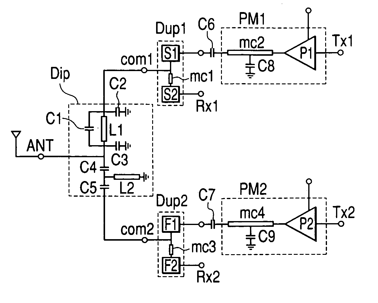
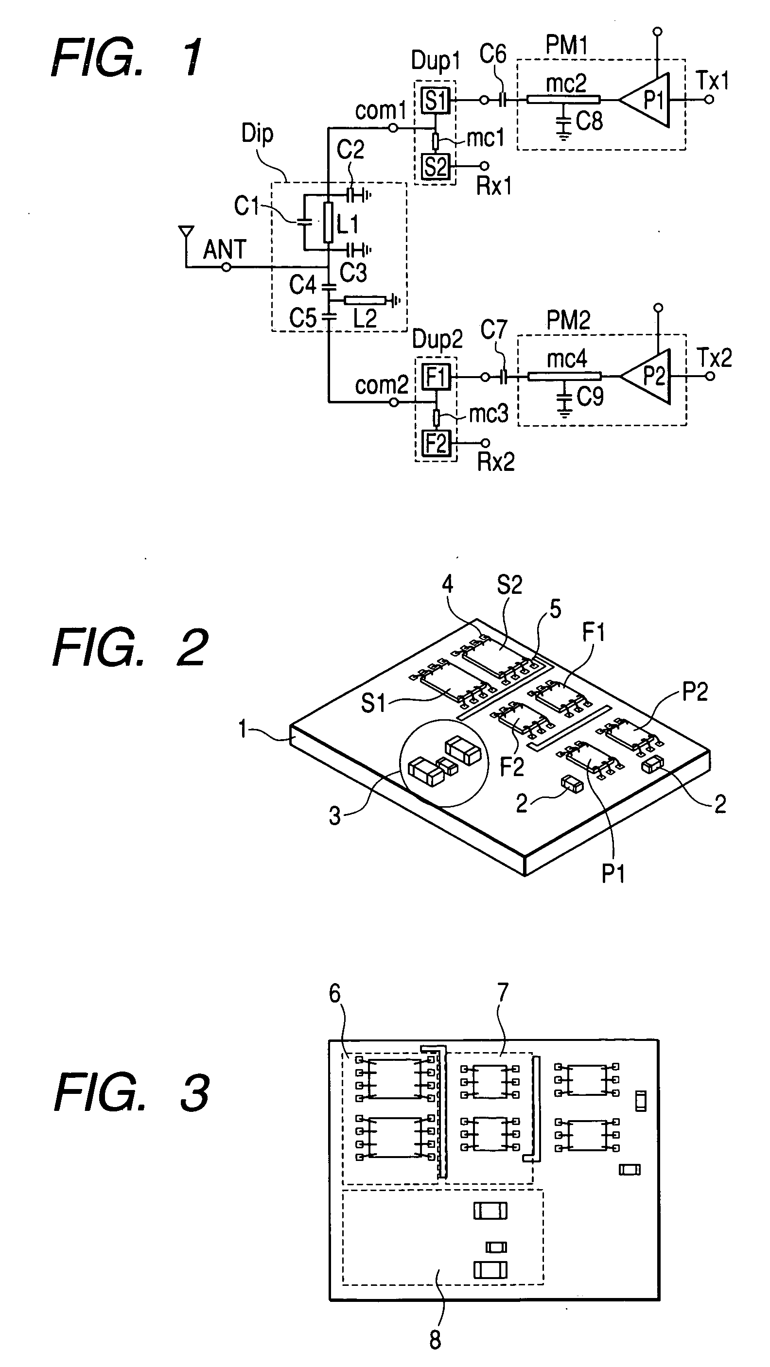
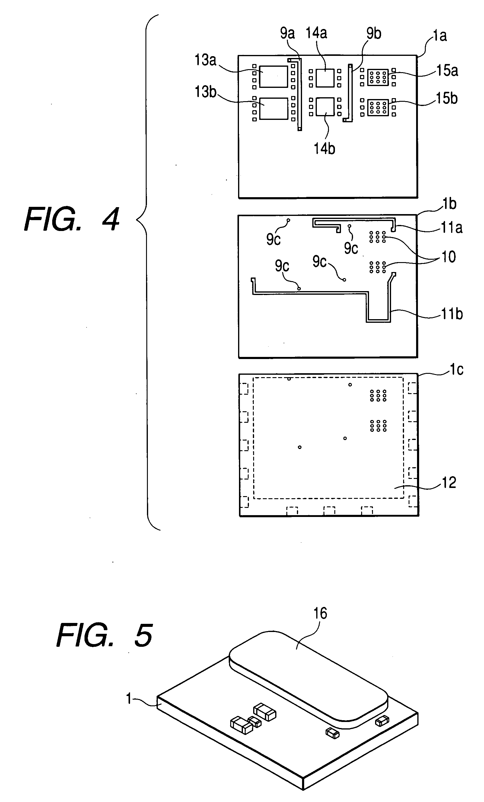
[0056]FIG. 1 is a circuit diagram of a multi-band transceiver, and FIG. 2 is a perspective view of this embodiment. FIG. 3 is a top view of this embodiment. FIG. 4 is an exploded view of a dielectric sheet that comprises a mounting substrate of this embodiment. FIGS. 5 and 6 are perspective views of this embodiment.

[0057] (Circuit Configuration)

[0058] The multi-band transceiver of this embodiment, as shown in FIG. 1, is provided with a branching filter Dip that is a frequency switching circuit, an antenna shared device Dup1 of a first communication system, a first amplifier PM1 for amplifying a transmitted signal of the first communication system, an antenna shared device Dup2 of a second communication system, and a second amplifier PM2 for amplifying the transmitted signal of the second communication system. The branching filter Dip connects a low-pass filter consisting...

modification example

[0073] (Modification Example)

[0074]FIG. 7 is a modification example of a mounting method of this embodiment. In this example, the amplifier circuit P1 is arranged adjacently to the FBAR filters F1 and F2, but the amplifier circuit P2 is arranged between the FBAR filters F1 and F2 via the amplifier circuit P1. In this case, when a first communication system is operating, the FBAR filters F1 and F2 are inserted between the amplifier circuit P1 and the SAW filters S1 / S2. Accordingly, the transfer of the heat from the amplifier P1 to the SAW filter S1 and S2 can be reduced.

[0075] Conversely, when a second communication system is operating, the amplifier circuit P1 is inserted between the amplifier circuit P2 and the FBAR filters F1 / F2. Accordingly, the transfer of the heat from the amplifier circuit P2 to the FBAR filters F1 and F2 can be reduced. This arrangement method can increase the distance between the filter and the amplifier circuit that correspond to each communication system,...

second embodiment

[0076] [Second Embodiment]

[0077] Next, a second embodiment according to the present invention is shown in FIGS. 8 to 10. FIG. 8 is a perspective view of this embodiment. FIG. 9 is a top view of this embodiment. FIG. 10 is a perspective view of this embodiment.

[0078] In this embodiment, as shown in FIG. 8, the filters S1 and S2 of the Dup1, the filters F1 and F2 of the Dup2, the amplifier circuit P1 of the amplifier PM 1, the amplifier circuit P 2 of the amplifier PM 2, a chip element 22 that forms a part of the matching circuits mc2 and mc4 of the amplifier, and a chip element 23 that forms a part of branching filters Dips on the top of amounting substrate 21 are mounted. In this embodiment, the amplifier circuits P1 and P2 and the SAW filters S1 and S2 are arranged on a diagonal line on the top of the mounting substrate 21, and the FBAR filters F1 and F2 are arranged in the traverse part between them. This arrangement method can arrange the FBAR filters F1 and F2 between the ampli...


PUM


Abstract

A multi-band transceiver has a function of sharing transmitted and received signals of multiple frequency bands by the same antenna. The multi-band transceiver mounts multiple filters that correspond to the multiple frequency bands and multiple amplifiers for amplifying the transmitted signals on the same substrate, and arranges the multiple filters in close vicinity to the amplifier in the order where the multiple filters are excellent in their temperature characteristic.

Description

FIELD OF THE INVENTION [0001] The present invention relates to a multi-band transceiver (transmitter-receiver) used in a front-end unit of a cellular phone or a radio communication device, and a radio communication device using the multi-band transceiver. BACKGROUND OF THE INVENTION [0002] In recent years, a cellular phone of a multi-band system that mounts transmitting-receiving systems of multiple communication systems in a single cellular phone, and can select them in accordance with regional characteristics and purposes for use is introduced. The cellular phone of the multi-band system must be provided with a transmitting-receiving circuit of each communication system and a branching circuit that branches a frequency band of the communication system. If each component is mounted individually, however, the cellular phone is made large, and leads to being increasingly expensive. [0003] Concerning this type of problem, for example, a multi-band transceiver shown in Japanese Patent ...

Claims


Application Information

Patent Timeline
Patent Type & Authority Applications(United States)
IPC IPC(8): H01P1/15H03H9/17H03H9/54H03H9/70H03H9/72H04B1/3822H04B1/50
CPCH04B1/005H04B1/52H04B1/406H04B1/0057H01L2224/48227H01L2924/19105H01L2223/6688
Inventor WADA, TOSHIYUKIFUKAMACHI, KEISUKEHAYASHI, KENJISHIBA, TAKASHIHOSAKA, NORIOKATAGISHI, MAKOTO
Owner HITACHI METALS LTD
Why Eureka
Try Eureka