Thin film electrode for high-quality GaN optical devices and method of fabricating the same

Active Publication Date: 2005-01-13
SAMSUNG ELECTRONICS CO LTD +1
View PDF7 Cites 12 Cited by
  • Summary
  • Abstract
  • Description
  • Claims
  • Application Information

AI Technical Summary

Benefits of technology

[0034] According to the present invention, after an alloy or a solid solution that forms a p-type thermo-electronic oxide thin film is deposited on a p-type GaN layer, annealing is carried out, thereby adjusting the energy band gap between the p-type GaN and the p-type thermo-electronic oxide and increasing the effective carrier density in a surface thereof. As a result, the Schottkey barrier height and width between the p-type GaN and the p-type thermo-electronic oxide are reduced. Therefore, there is provided a high-quality ohmic contact system having high transmissivity

Problems solved by technology

However, two problems heretofore hinder a p-type GaN ohmic contact from ensuring high quality contact.
Thus, a Mg—H complex having an electrically insulating characteristic is formed, which results in a low effective carrier density and a high surface resistance value.
Therefore, it is difficult to form a high-quality ohmic contact.
Actually, the low hole injection makes the fabrication

Method used


Image

  • Thin film electrode for high-quality GaN optical devices and method of fabricating the same
  • Thin film electrode for high-quality GaN optical devices and method of fabricating the same
  • Thin film electrode for high-quality GaN optical devices and method of fabricating the same

Examples


experiment 1

[0061] A surface of the p-type GaN semiconductor is cleaned with trichloroethylene, acetone, methanol, and pure water within an ultrasonic wave cleaner at a temperature of 60° C. for five minutes. Then, hard baking is performed at 100° C. for 10 minutes so as to remove any water remaining in the specimen. Thereafter, a photoresist is spin-coated at 4,000 rpm, which is then soft baked at a temperature of 88° C. for 10 minutes. After aligning the mask and specimen so as to develop a mask pattern, they are exposed to ultraviolet rays at an intensity of 22.8 mW for 10 seconds. The specimen is sintered in a solution obtained by mixing a development solution and distilled water in a ratio of 1:4, thereby being developed for 15 seconds or so.

[0062] Then, the resultant structure is sintered for 5 minutes in order to eliminate a contaminated layer on the developed specimen using a buffered oxide etch (BOE) solution. Using an electron beam depositor, a Cu—La solid solution and Au are respect...

experiment 2

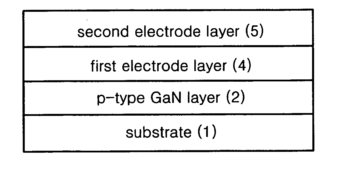
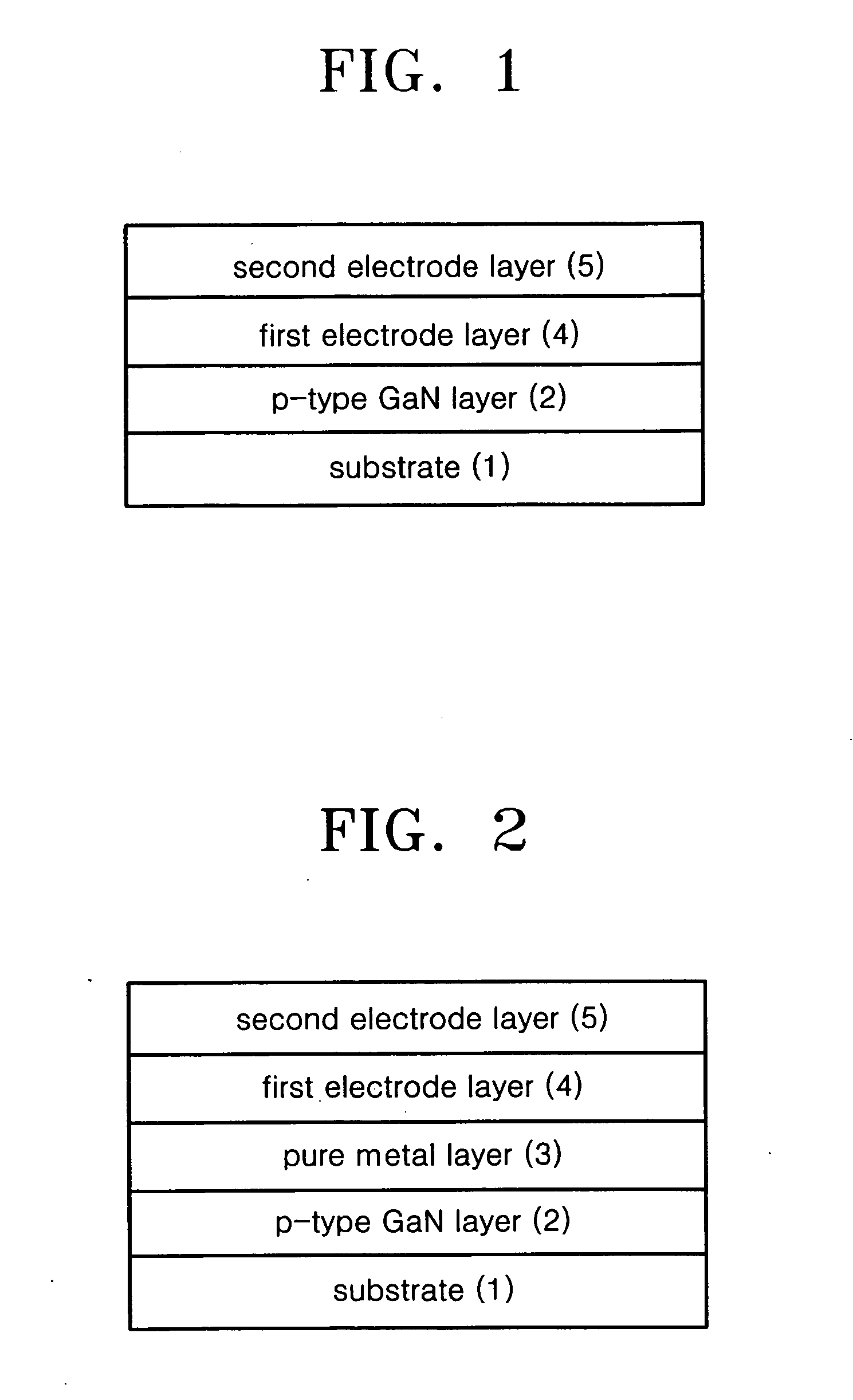
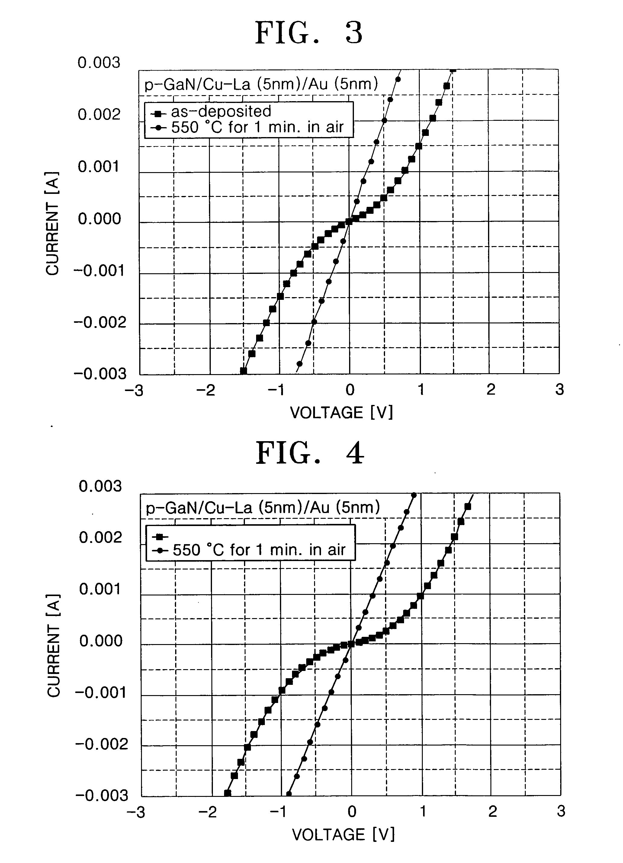
[0063] The process until depositing an electrode material using an electron beam depositor is identical with that of the foregoing Experiment 1. Here, the electron beam depositor is used for stacking a Pd / Cu—La solid solution / Au combination to a thickness of 50 Å, respectively. Lift-off is performed using acetone. The specimen is put in a quick heater at 550° C. for 1 minute in an air environment, thereby fabricating a metal thin film of forming the ohmic contact.

[0064] According to the present invention, the transparent p-type thermo-electronic conductive oxide thin films for LEDs and LDs of high efficiency using the ohmic contact formation may effect excellent electrical and optical characteristics such as low specific contact resistance, excellent current-voltage characteristics, a good surface condition, and high transparency. Therefore, the electric and optical efficiencies of future LEDs and LDs are increased so that the transparent p-type thermo-electronic conductive oxide t...


PUM

PropertyMeasurementUnit
Temperatureaaaaaaaaaa
Fractionaaaaaaaaaa
Timeaaaaaaaaaa

Abstract

A thin film electrode for ohmic contact of a p-type GaN semiconductor includes first and second electrode layers sequentially stacked on a p-type GaN layer. The first electrode layer may include an Ni-based alloy, a Cu-based alloy, a Co-based alloy, or a solid solution capable of forming a p-type thermo-electronic oxide or may include a Ni-oxide doped with at least one selected from Al, Ga, and In. The second electrode layer may include at least one selected from the group consisting of Au, Pd, Pt, Ru, Re, Sc, Mg, Zn, V, Hf, Ta, Rh, Ir, W, Ti, Ag, Cr, Mo, Nb, Ca, Na, Sb, Li, In, Sn, Al, Ni, Cu, and Co. Furthermore, a method of fabricating the thin film electrode is provided.

Description

[0001] This application claims the priority of Korean Patent Application No. 2003-47273, filed on Jul. 11, 2003 with the Korean Intellectual Property Office, the disclosure of which is incorporated herein in its entirety by reference. BACKGROUND OF THE INVENTION [0002] 1. Field of the Invention [0003] The present invention relates to a thin film electrode and a method of manufacturing the same capable of forming high-quality ohmic contact, which is one key technique in fabricating light emitting diodes (LEDs) and laser diodes (LDs) that emit short waves of blue, green and ultraviolet rays using a GaN semiconductor. [0004] 2. Description of the Related Art [0005] When embodying optical devices such as LEDs and LDs using a GaN semiconductor, it is important to form a high-quality ohmic contact between a semiconductor and an electrode. [0006] In the case of a conventional p-type GaN semiconductor, a Ni-based thin metal film structure, i.e., a thin metal film of Ni / Au, was widely used. ...

Claims


Application Information

Patent Timeline
IPC IPC(8): H01L21/28H01L21/285H01L29/20H01L29/45H01L33/32H01L33/42
CPCH01L21/28575H01L29/2003H01L29/452H01L33/0095H01L33/32H01L2924/0002H01L33/42H01L2924/00
Inventor LEEM, DONG-SEOKSONG, JUNE-OKIM, SANG-HOSEONG, TAE-YEON
Owner SAMSUNG ELECTRONICS CO LTD
Why Eureka
Try Eureka