Chloride melt process for the separation and recovery of zinc

a chloride melt and zinc technology, applied in the field of chloride melt process for the separation and recovery of zinc, can solve the problems of consuming a lot of zinc metal in the cementation step, the liquid purification step is rather complicated, and the leaching step is long and complicated, so as to avoid the melting of zinc cathodes, improve the control of residues, and improve the effect of reducing the number of sintering steps

Inactive Publication Date: 2005-01-13
UMICORE AG & CO KG
View PDF8 Cites 8 Cited by
  • Summary
  • Abstract
  • Description
  • Claims
  • Application Information

AI Technical Summary

Benefits of technology

It is an object of the present invention to overcome the disadvantages of the above mentioned methods. Our main goal is to have a better control of residues. This means that clear-cut, single step separations of the different elements present in the feed are required, in order to avoid as much as possible the production of residues that must be disposed of, and to favour the production of well marketable exits for the separated by-products. Another aim is to allow a high flexibility in the feed, i.e. to be able to use, separately or together, various zinc-bearing primary or secondary materials. Another advantage over the sulphate process is that the electrolysis produces molten zinc which can be directly cast, thus avoiding the melting of zinc cathodes. Yet another advantage is the overall lower energy consumption of the process. Beside an economical interest, this is also important from the environmental point of view, since less energy means less production of greenhouse effect generating gases.

Problems solved by technology

In consequence, the liquor purification step is rather complicated, involves a lot of different process steps and produces many different types of residues.
Another difficulty of the sulphate process is that in order to achieve maximum recovery yields of zinc and also of other valuable impurities such as copper and cadmium, the leaching step is long and complicated, involving successive leaching operations at different acidities and temperatures.
First, a lot of zinc metal is consumed in the cementation step, whether in the dry or the wet embodiment.
Also, as the molten zinc chloride must be very pure for the electrolysis, the totality of the other elements must be removed from the flow, which implies a non-selective output which is difficult to valorise.
These operations are not economically interesting.

Method used


Image

  • Chloride melt process for the separation and recovery of zinc
  • Chloride melt process for the separation and recovery of zinc
  • Chloride melt process for the separation and recovery of zinc

Examples


example 1

Chlorination of Zinc Blende

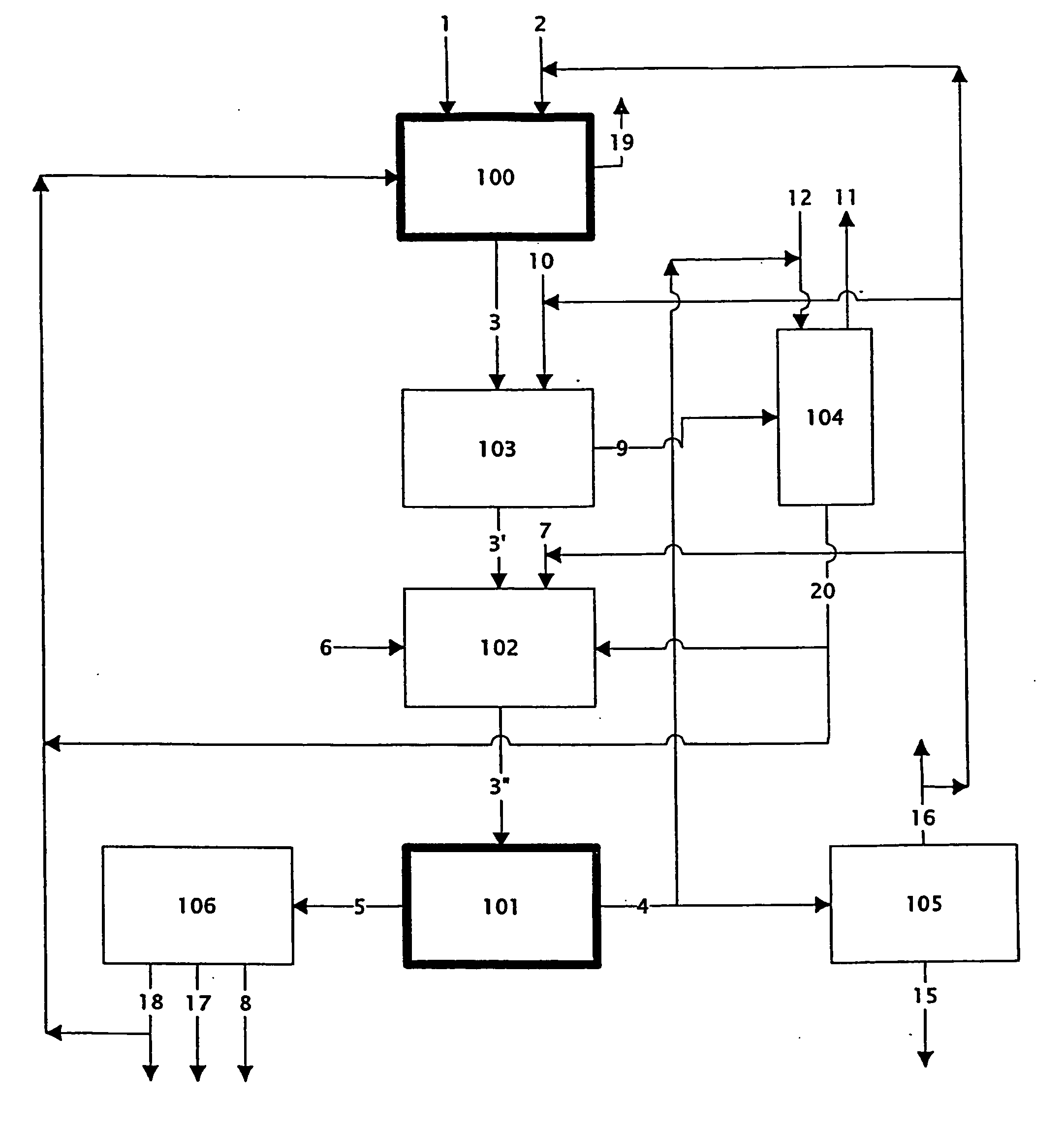
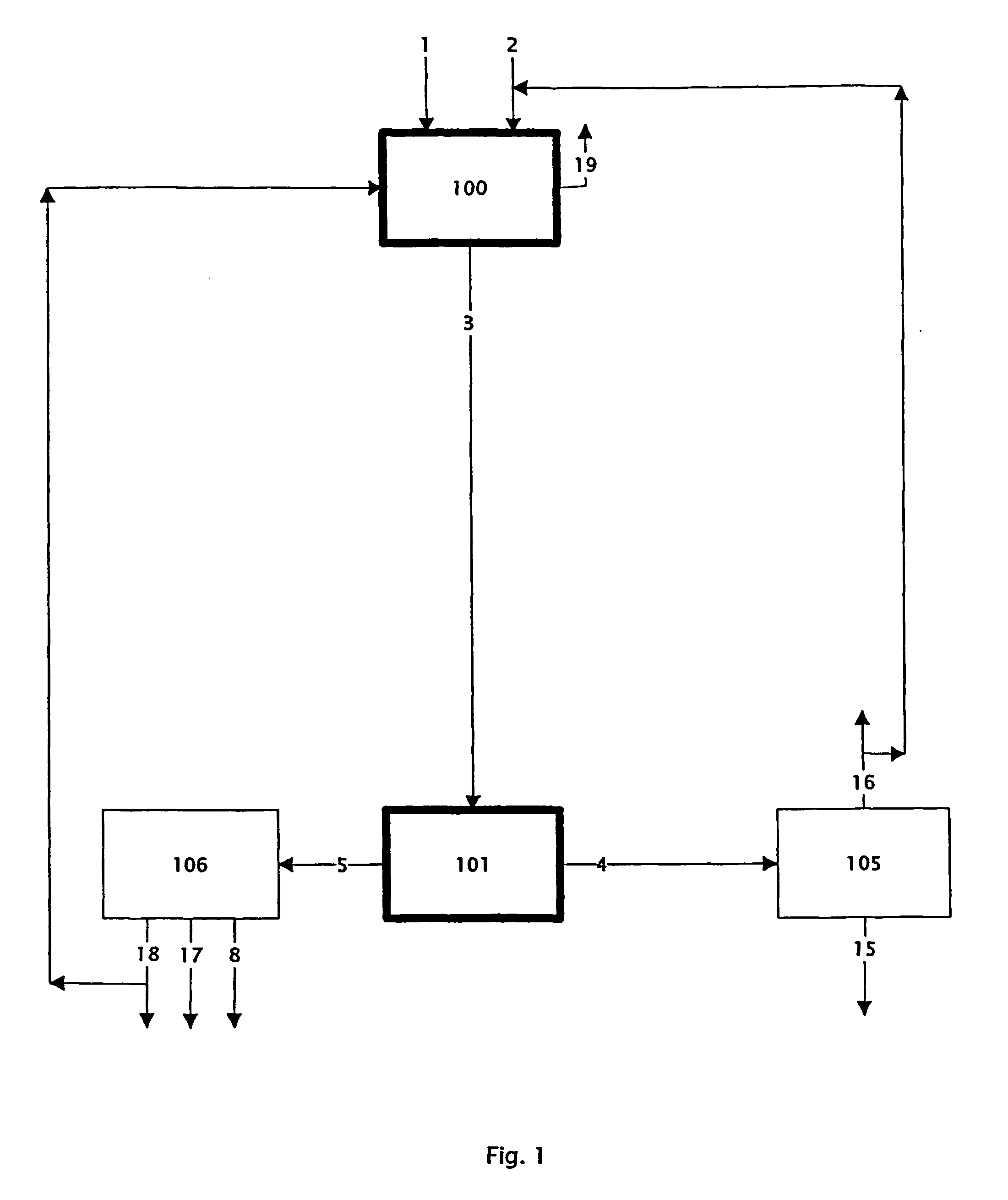
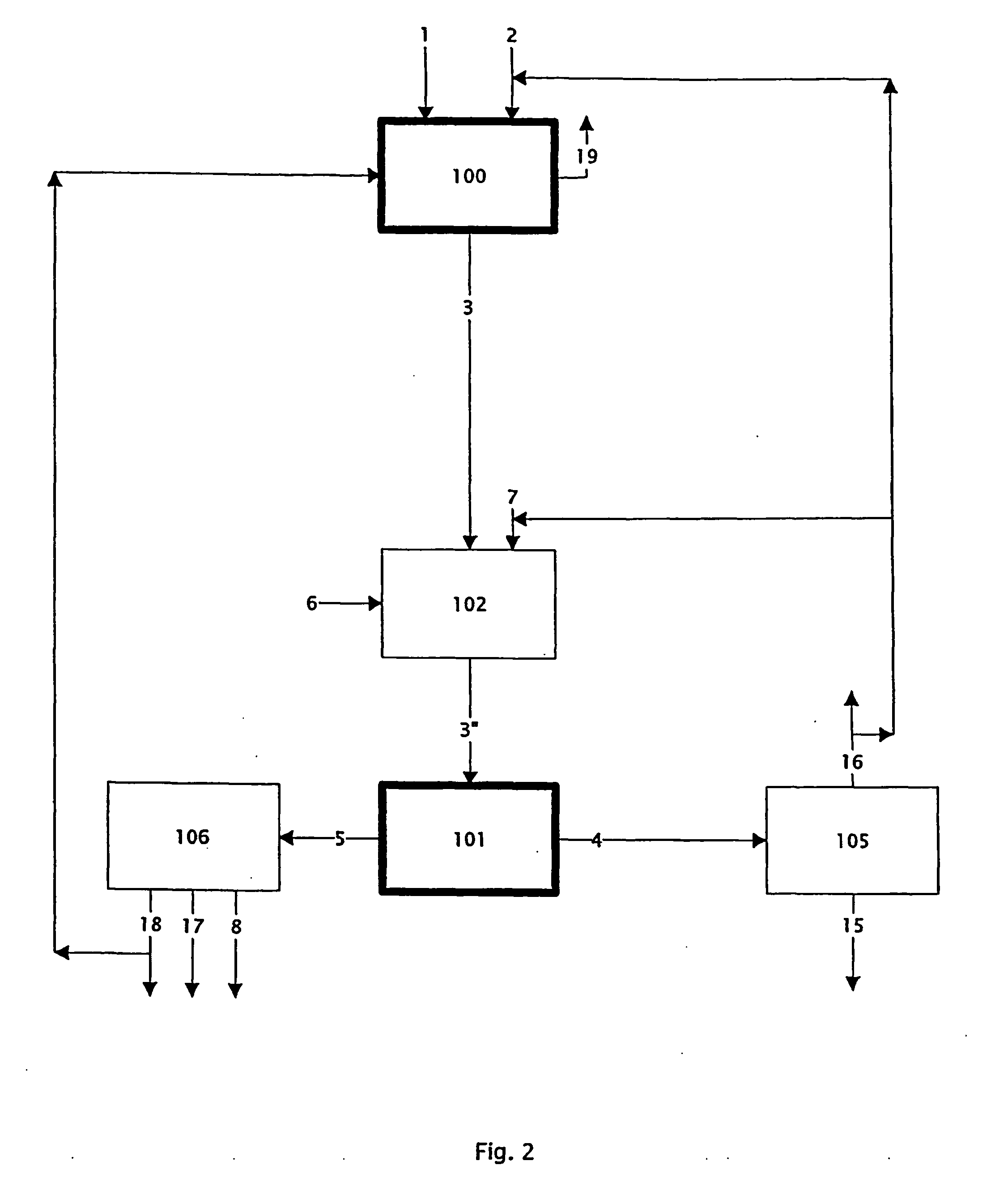
This example demonstrates the ability of the process to leach a blende concentrate (process step 100: reacting Zn bearing material with chlorinating agent).

2 kg of a molten solvent was prepared by mixing chloride salts in a quartz reactor. The composition of the solvent was: 51 mol % ZnCl2, 11.3 mol % PbCl2, 3 mol % CdCl2, 2 mol % KCl, 12.1 mol % NaCl, 17.4 mol % CaCl2, 2.4 mol % CuCl, 0.8 mol % BaCl2. The mixture was heated to 600° C. under nitrogen. 1.6 kg of a blende concentrate was gradually added to the melt. The blende contained 50.6 wt % Zn, 9.2 wt % Fe, 1.8 wt % Pb, 0.1 wt % Cd, 0.23 wt % Cu, 33 wt % S. Chlorine gas was introduced by a quartz injection tube located at the bottom of the reactor, at a rate of 500 cc / min during 13 h. Sulphur was evolved from the reactor and collected in a condenser.

In order to evaluate the chlorination, the resulting melt was dissolved in 5 l of a NaCl 5 M solution, which favours the dissolution of the formed ch...

example 2

Chlorination of an Oxide Feed

This example demonstrates the ability of the process to leach an oxide feed (process step 100: reacting Zn bearing material with chlorinating agent).

2 kg of a molten solvent was prepared by mixing chloride salts in a quartz reactor. The composition of the solvent was: 51 mol % ZnCl2, 11.3 mol % PbCl2, 3 mol % CdCl2, 2 mol % KCl, 12.1 mol % NaCl, 17.4 mol % CaCl2, 2.4 mol % CuCl, 0.8 mol % BaCl2. The mixture was heated to 600° C. under nitrogen. 1 kg of Waelz oxide was gradually added to the melt. The oxide contained 56 wt % Zn, 3.32 wt % Fe, 7.9 wt % Pb. Chlorine gas was introduced by a quartz injection tube located at the bottom of the reactor, at a rate of 500 cc / min during 10 h.

In order to evaluate the chlorination, the resulting melt was dissolved in 5 l of a NaCl 5 M solution, which favours the dissolution of the formed chlorides. The solid residue was filtered out of the solution and analysed for its base metals content. Table 2 shows the ext...

example 3

Fe(III) Chloride Elimination

This example demonstrates the ability of the process to eliminate iron from the melt (process step 103: volatilising Fe as Fe(III) chloride).

A melt was prepared by chlorination of 2 kg of zinc blende with chlorine gas, in 1.8 kg of molten solvent. The zinc blende and the molten solvent had the same composition as in Example 1. After the chlorination, the melt contained 4 wt % of Fe, which is too much to be blocked as Fe2O3 by addition of e.g. ZnO, as explained above.

Chlorine gas was injected in the melt at a flow rate of 500 ml / min during 6 h. The temperature of the melt was 620° C. The experiment was stopped when almost no brown fumes (indicating the presence of Fe(III) chloride) were produced anymore. The analysis of the melt showed that the residual Fe content was 0.21 wt %, and thus that 95.8% of the Fe had been eliminated. The final Fe content is well below the limit of 2 wt % and can thus be blocked as an oxide. In those conditions, the contam...


PUM

PropertyMeasurementUnit
temperatureaaaaaaaaaa

Abstract

Process for the production of ZnCl2 from a Zn bearing primary and/or secondary material comprising the steps of reacting the Zn bearing material with a chlorinating agent such as Cl2 to convert metals into chlorides and vaporising the volatile components of the reaction product at a temperature between the melting point of said reaction product and the boiling point of ZnCl2, thereby recovering a Zn rich chlorinated melt, and thereafter distilling ZnCl2 from this Zn rich chlorinated melt, thereby recovering purified ZnCl2 and a Zn-depleted chlorinated melt.

Description

FIELD OF THE INVENTION According to the present invention, a process is provided for the separation and recovery of metals, especially zinc, from zinc bearing primary and / or secondary material. More specifically, the process of the present invention relates to the conversion of the metals in the feed material to metal chlorides and subsequent recovery of the zinc and optionally other metals. BACKGROUND OF THE INVENTION Most present processes for zinc production require oxidic raw materials. Nowadays, the most widely used process for zinc production is the sulphate process which represented 80% of total world production in 1997. It consists of the steps of roasting, leaching, liquor purification, electro-deposition, melting and casting. The most abundant natural raw material is zinc blende (ZnS), which must be roasted to ZnO as a first step. Of course, zinc oxide recycled from other industries can be used directly without roasting. The zinc electro-deposition is readily disturbed ...

Claims


Application Information

Patent Timeline
Patent Type & Authority Applications(United States)
IPC IPC(8): C22B19/02C01G9/04C22B1/00C22B1/08C22B3/44C22B19/00C22B19/04C25C3/34
CPCC01G9/04C22B1/08C25C3/34C22B19/04C22B19/00Y02P10/20
Inventor VANDENHAUTE, JORISROBERT, ERIC
Owner UMICORE AG & CO KG
Why Eureka
Try Eureka