Organic light emitting diode backlight integrated LCD

a light-emitting diode backlight and organic technology, applied in non-linear optics, instruments, optics, etc., can solve the problems of inconvenient use, large moisture content, and appearance of fringes and rings, and achieve the effects of less moisture, enhanced oled life, and more durabl

Inactive Publication Date: 2005-01-13
ORGANIC LIGHTING TECH
View PDF7 Cites 73 Cited by
  • Summary
  • Abstract
  • Description
  • Claims
  • Application Information

AI Technical Summary

Benefits of technology

[0016] As the Optiva's TCF polarizer layer is internal to the LCD, the integrated structure is more durable because the external surface of LCD is glass instead of plastic lamination. Additionally, the life of OLED is enhanced because the glass surface de-sorbs less moisture compared to plastic. Due to the elimination of one substrate and inclusion of internal polarizer, the integrated structure is 50% thinner than the conventional structure and reduces the manufacturing costs. In the integrated structure, the light coupling, from backlight device to LCD, is maximum. For LCDs that do not incorporate polarizers, LCD fabrication is simpler in that planarization layers and TCF layers can be eliminated. In an alternate sequence of fabrication, for LCDs that do not employ active matrix substrates, OLED backlight device can be fabricated first and the LCD fabrication can...

Problems solved by technology

It has also been observed that the variation in gap between the backlight and LCD causes optical defects like, appearance of fringes and rings.
Further, the phosphor coated on one of the electrodes will erode away due to sputtering during operation and render the device useless.
One drawback of this in...

Method used


Image

  • Organic light emitting diode backlight integrated LCD
  • Organic light emitting diode backlight integrated LCD
  • Organic light emitting diode backlight integrated LCD

Examples


Embodiment Construction

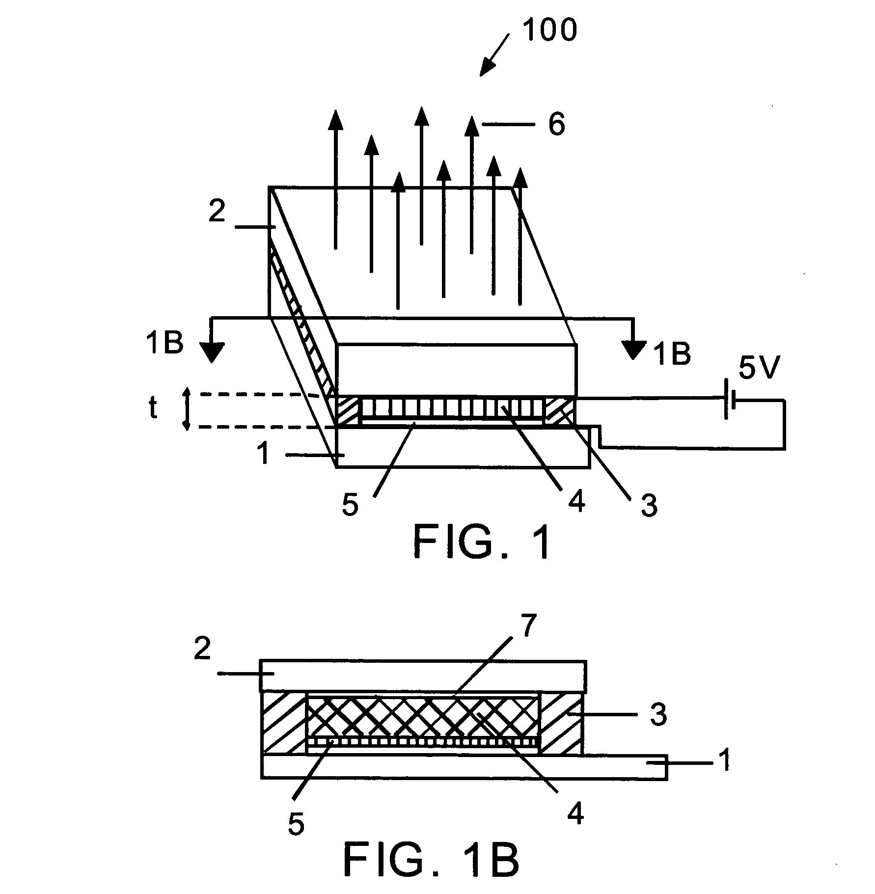
[0030]FIG. 1 shows the isometric view of an OLED backlight device 100. An organic multi-layer stack 4 is enclosed between top glass substrate 2 and bottom glass substrate 1, more precisely cover glass. The thickness of the organic layer is denoted by t and is around 125 nm to 200 nm. The stack 4 is sealed all around by a perimeter seal 3, which is hermetic to prevent moisture and Oxygen entering the device. When a voltage of 5V is applied across the stack 4, through the reflective cathode 5 and the transparent anode, not shown in FIG. 1, the organic stack emits visible light 6. Also not shown in FIG. 1 is a gap between cathode 5 and bottom substrate 1. FIG. 1B is the cross section taken from FIG. 1. The OLED stack, enclosed between the top glass substrate 2 and bottom substrate 1 and sealed at the perimeter by the seal 3, contains a cathode 5 and an anode 7 that inject electrons and holes respectively to the organic stack 4. The anode 7 is usually of Indium Tin Oxide (ITO). It can b...


PUM


Abstract

An organic light emitting diode (OLED) backlight integrated LCD comprising three substrates of which one substrate is shared by LCD and OLED backlight. The shared substrate has two surfaces of which one surface contains, among other layers, a transparent electrode, an internal polarizer and an aligning layer for liquid crystal and faces the top substrate of LCD that also contains identical layers. A thin liquid crystal film is sandwiched between the two substrates containing the said layers. The second surface of said shared substrate contains active organic layers that include an anode and a cathode and faces the bottom substrate of OLED backlight. The two surfaces of the shared substrate are hermetically sealed to the other two substrates of LCD and OLED. When electrically activated the OLED backlight device substantially couples and transmit its generated light in to the LCD.

Description

CROSS REFERENCE TO RELATED APPLICATION [0001] Benefit of Provisional patent Application No. 60 / 485,571 filed Jul. 8, 2003, Docket No. OLIT1140 [0002] Provisional Patent Application No. 60 / 461,098 filed Apr. 8, 2003; also filed as full patent on Mar. 31, 2004 [0003] U.S. Pat. No. 6,208,391—Fukushima, et al. Mar. 27, 2001 [0004] U.S. Pat. No. 5,754,159—Wood et. al, May 19, 1998 [0005] U.S. Pat. No. 6,542,145—Reisinger et. al, Apr. 1, 2003 [0006] U.S. Pat. No. 6,639,349—Bahadur, Oct. 28, 2003OTHER PUBLICATIONS [0007] Y. Bobrov, L. Fennell, P. Lazarev, M. Paukshto, S. Remizov “Manufacturing of a Thin-Film LCD”Journal of the SID, 10 / 4, 317-321, 2002. STATEMENT REGARDING FEDERALLY SPONSORED RESEARCH OR DEVELOPMENT [0008] Not Applicable REFERENCE TO SEQUENCE LISTING, A TABLE, OR A COMPUTER PROGRAM LISTING COMPACT DISK APPENDIX [0009] Not Applicable BACKGROUND OF THE INVENTION [0010] Transmissive Liquid Crystal Displays (LCDs) employed in display systems for various applications require a b...

Claims


Application Information

Patent Timeline
IPC IPC(8): G02F1/13357H01L27/32H01L51/00H01L51/52
CPCG02F1/133603H01L27/3232Y02E10/549H01L51/5237H01L51/0096H10K59/50H10K77/10H10K59/871H10K50/841
Inventor ANANDAN, MUNISAMY
Owner ORGANIC LIGHTING TECH
Why Eureka
Try Eureka