Chemical reaction apparatus

a chemical reaction and apparatus technology, applied in the direction of chemistry apparatus and processes, physical/chemical process catalysts, hydrogen separation using solid contact, etc., can solve the problems of carbonate moving to the pores of solid catalysts and cloggings, and deteriorating the capability of solid catalysts and carbon dioxide absorbents, so as to improve the hydrogen yield and not deteriorate the hydrogen yield

Inactive Publication Date: 2005-02-03
KK TOSHIBA
View PDF3 Cites 13 Cited by
  • Summary
  • Abstract
  • Description
  • Claims
  • Application Information

AI Technical Summary

Benefits of technology

[0013] The present invention is directing to provide a chemical reaction apparatus that does not deteriorate the hydrogen yield when the apparatus is used for a long period as compared with a conventional apparatus in a chemical r

Problems solved by technology

However, the method is disadvantageous in that when the solid catalyst is mixed with the carbon dioxide absorbent and the mixture thereof is used for the filling, their capability is deteriorated when they are used for a long period.
That is, since the solid catalyst is ordinarily a porous member and lithium silicate, which is suitable as the carbon dioxide absorbent, generates molten carbonate in use, when absorption and regeneration are executed, the carbonate moves to the pores of the solid catalyst and clogs them.
When the carbon dioxide absorbent is used for a long period while repeating the absorption and the regeneration therein, the effect of movement of

Method used


Image

  • Chemical reaction apparatus
  • Chemical reaction apparatus
  • Chemical reaction apparatus

Examples


first embodiment

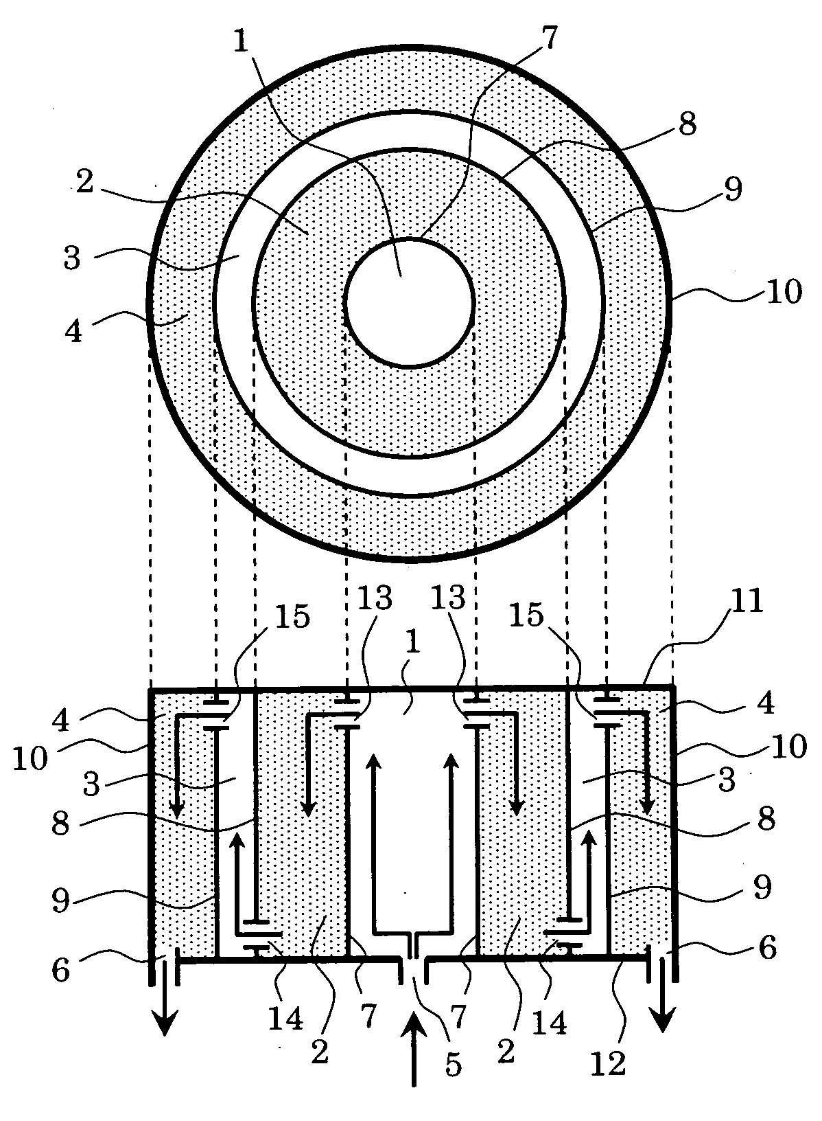
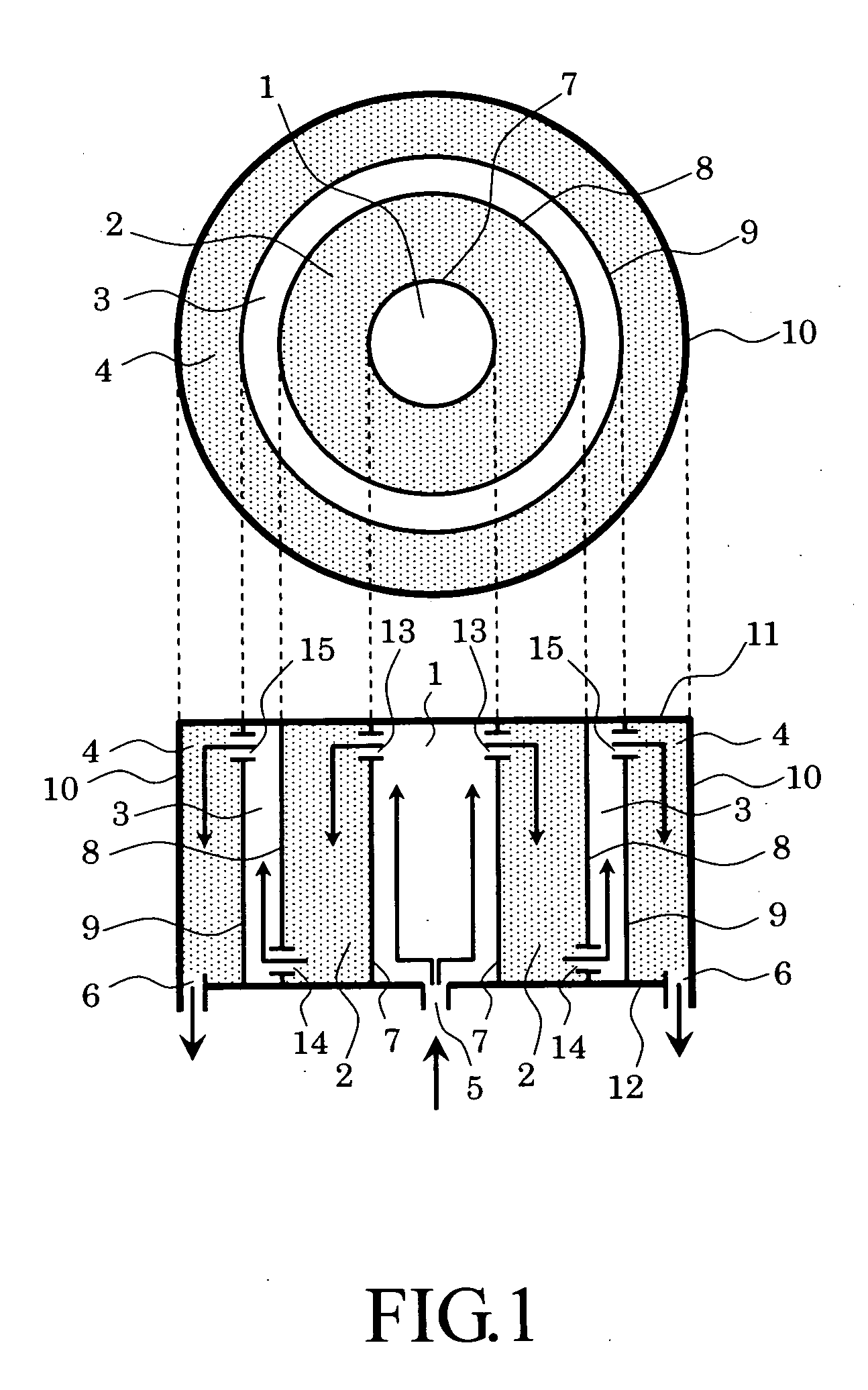
[0031]FIG. 1 is a schematic view showing a first embodiment of a chemical reaction apparatus of the present invention. In FIG. 1, an upper figure shows a sectional view of the chemical reaction apparatus when it is observed from an upper direction, and a lower figure is a sectional view thereof when it is observed from a lateral direction.

[0032] The chemical reaction apparatus includes first and second reaction chambers 1 and 3 each of which has a catalyst installed therein so that the catalysts cause a reaction for generating a gas containing hydrogen as a main product and carbon dioxide as a by-product from a material gas and first and second carbon dioxide absorbent chambers 2 and 4 acting as regions each of which has a carbon dioxide absorbent installed therein.

[0033] The first reaction chamber 1 has a material gas introduction pipe connected thereto. This pipe acts as a material gas introduction port 5. The second carbon dioxide absorbent chamber 4 has a generated gas exhaust...

second embodiment

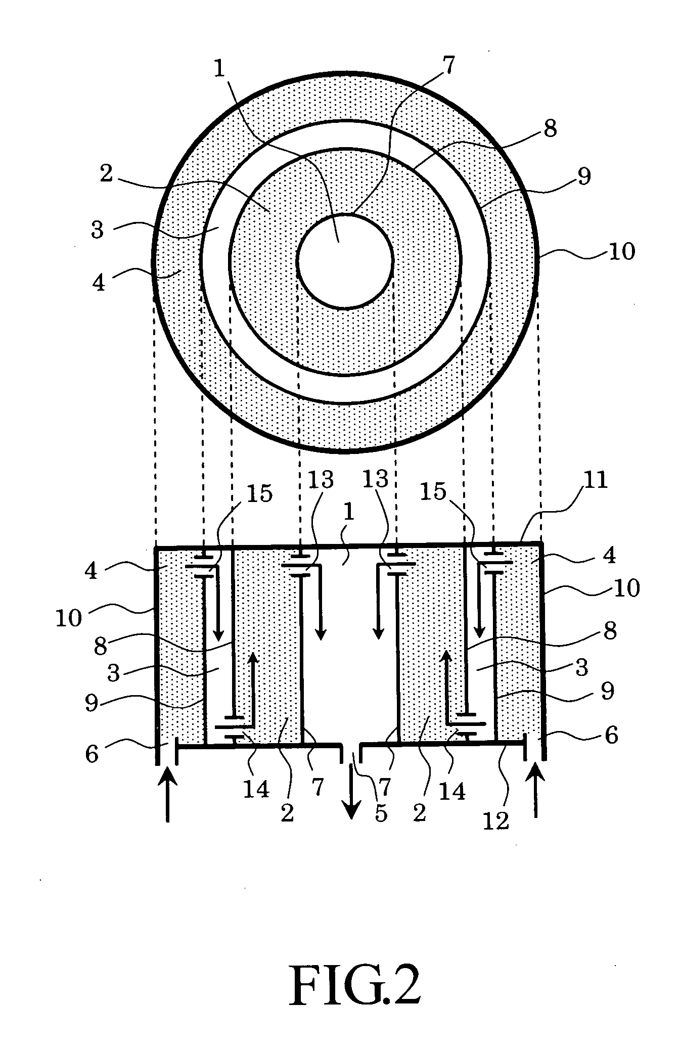
[0065]FIG. 3 is a schematic view showing a second embodiment of the chemical reaction apparatus of the present invention. In FIG. 3, an upper figure shows a sectional view of the chemical reaction apparatus when it is observed from an upper direction, and a lower figure is a sectional view thereof when it is observed from a lateral direction. The second embodiment has the same arrangement as that of the first embodiment except that the directions in which gases flow are changed by changing the positions of gas introduction and discharge ports. The chemical reaction apparatus includes first and second reaction chambers 1 and 3 acting as catalyst regions each of which is filled with a catalyst so that the catalysts cause a reaction for generating a gas containing hydrogen as a main product and carbon dioxide as a by-product from a material gas and first and second carbon dioxide absorbent chambers 2 and 4 acting as carbon dioxide absorbent regions each of which is filled with a carbon...

example 1

[0086] Hydrogen was generated using the chemical reaction apparatus shown in FIG. 1.

[0087] Each of reactors had inner walls 7, 8, 9 and an outer wall 10 each formed in a cylindrical shape, the inner wall 7 had an inside diameter of 0.25 m, the inner wall 8 had an inside diameter of 0.75 m, the inner wall 9 had an inside diameter of 0.80 m, and the outside wall 10 had an inside diameter of 1.05 m. The inner walls 7, 8, 9 had a thickness set to about 0.005 m. Further, each of the reactors had a bottom and a ceiling therein which were separated from each other by a distance of 1.7 m, holes each having a diameter of 3 mm and distributed uniformly around the inner walls 7 and 9 in a band shape at a position of 0.1 m to 0.2 m below the ceiling, and holes each having a diameter of 3 mm and distributed uniformly around the inner wall 8 in a band shape at a position of 0.05 m to 0.15 m above the bottom.

[0088] Alumina particles, which carried about 20 wt % of metal nickel and had an average...


PUM

PropertyMeasurementUnit
Electrical conductivityaaaaaaaaaa

Abstract

A chemical reaction apparatus includes a reaction chamber and a carbon dioxide absorbent chamber disposed behind the reaction chamber in adjacent to it. The reaction chamber generates a gas containing hydrogen and carbon dioxide from the material gas, and the carbon dioxide absorbent chamber absorbs carbon dioxide from the gas generated from the reaction chamber.

Description

CROSS-REFERENCE TO RELATED APPLICATION [0001] This application is based upon and claims the benefit of priority from the prior Japanese Patent Applications No. JP2003-184783, filed on Jun. 27, 2003; the entire contents of which are incorporated herein by reference. FIELD OF THE INVENTION [0002] The present invention relates to a chemical reaction apparatus for generating hydrogen from a material gas. More particularly, the present invention relates to a chemical reaction apparatus capable of increasing the recovery ratio of a main product by improving a reaction efficiency by separating hydrogen generated as a main product from the material gas from carbon dioxide generated as a by-product. DESCRIPTION OF THE BACKGROUND [0003] In general, many of reactions, which generate carbon dioxide as a by-product in a reaction for generating hydrogen as a main product from a raw material containing carbon monoxide and from a raw material containing carbon hydride, are well known, and these rea...

Claims


Application Information

Patent Timeline
IPC IPC(8): B01J8/00B01J8/04B01J8/06C01B3/38C01B3/56C01B3/58
CPCB01J8/009B01J8/0465B01J2208/025C01B3/38C01B2203/82C01B2203/0233C01B2203/0425C01B2203/0475C01B3/56
Inventor ESSAKI, KENJIKATO, MASAHIROYOSHIKAWA, SAWAKONAKAGAWA, KAZUAKI
Owner KK TOSHIBA
Why Eureka
Try Eureka