
Reformation of hydrogen-containing fluids in a cyclic flow reactor

a hydrogen-containing fluid and cyclic flow reactor technology, applied in the direction of liquid chemical processes, gas-gas reaction processes, liquid-gas reactions of thin-film type, etc., can solve the problems of less common, less common, and the inability of ultra-rich mixtures to produce self-sustained flames, etc., to achieve reform reaction, increase the efficiency of the reactor, and high values

Active Publication Date: 2012-12-04
INNOVATIVE ENERGY SOLUTION
View PDF13 Cites 6 Cited by
  • Summary
  • Abstract
  • Description
  • Claims
  • Application Information

AI Technical Summary

Benefits of technology

This approach eliminates the need for continuous external energy, achieves high hydrogen yield, and effectively reforms sulfur-containing fuels, overcoming efficiency and catalyst deactivation issues in existing methods.

Problems solved by technology

Ultra-rich mixtures do not normally produce self-sustained flames without the aid of external energy sources or preheating the mixture.
Although the partial oxidation process does not need an external source of heat since it is exothermic, it is still less common than steam reforming since it is generally less efficient than steam reforming particularly at large scale.
Due to its catalytic nature, the autothermal process falls under the same constraints as the steam reforming process in that the catalyst bed is susceptible to poisoning and deactivation by sulfur, carbon, and other poisons in the feed stream.
For example, the low heat content of H2S precludes obtaining very high temperature in the partial oxidation regime.

Method used


Image

  • Reformation of hydrogen-containing fluids in a cyclic flow reactor
  • Reformation of hydrogen-containing fluids in a cyclic flow reactor
  • Reformation of hydrogen-containing fluids in a cyclic flow reactor

Examples


example

Hydrogen Sulfide Reformation

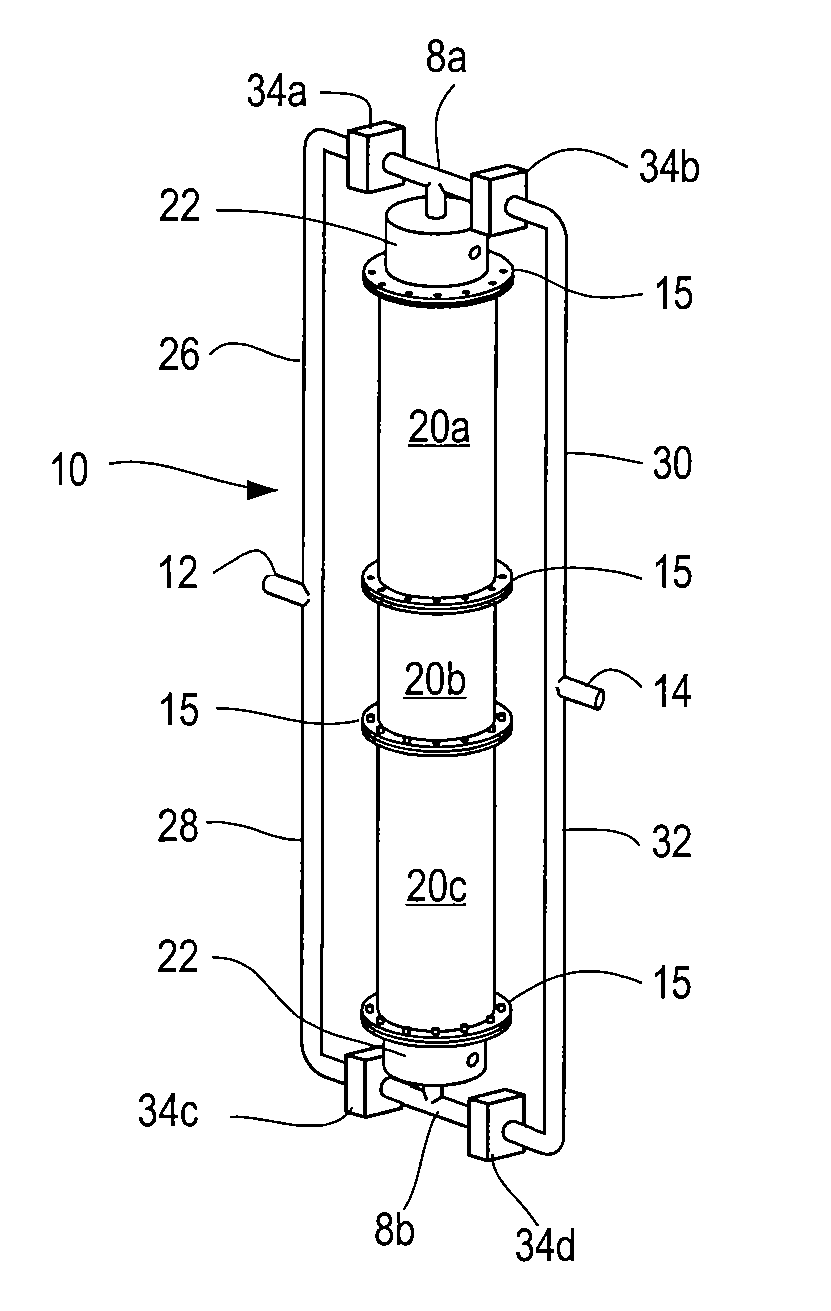
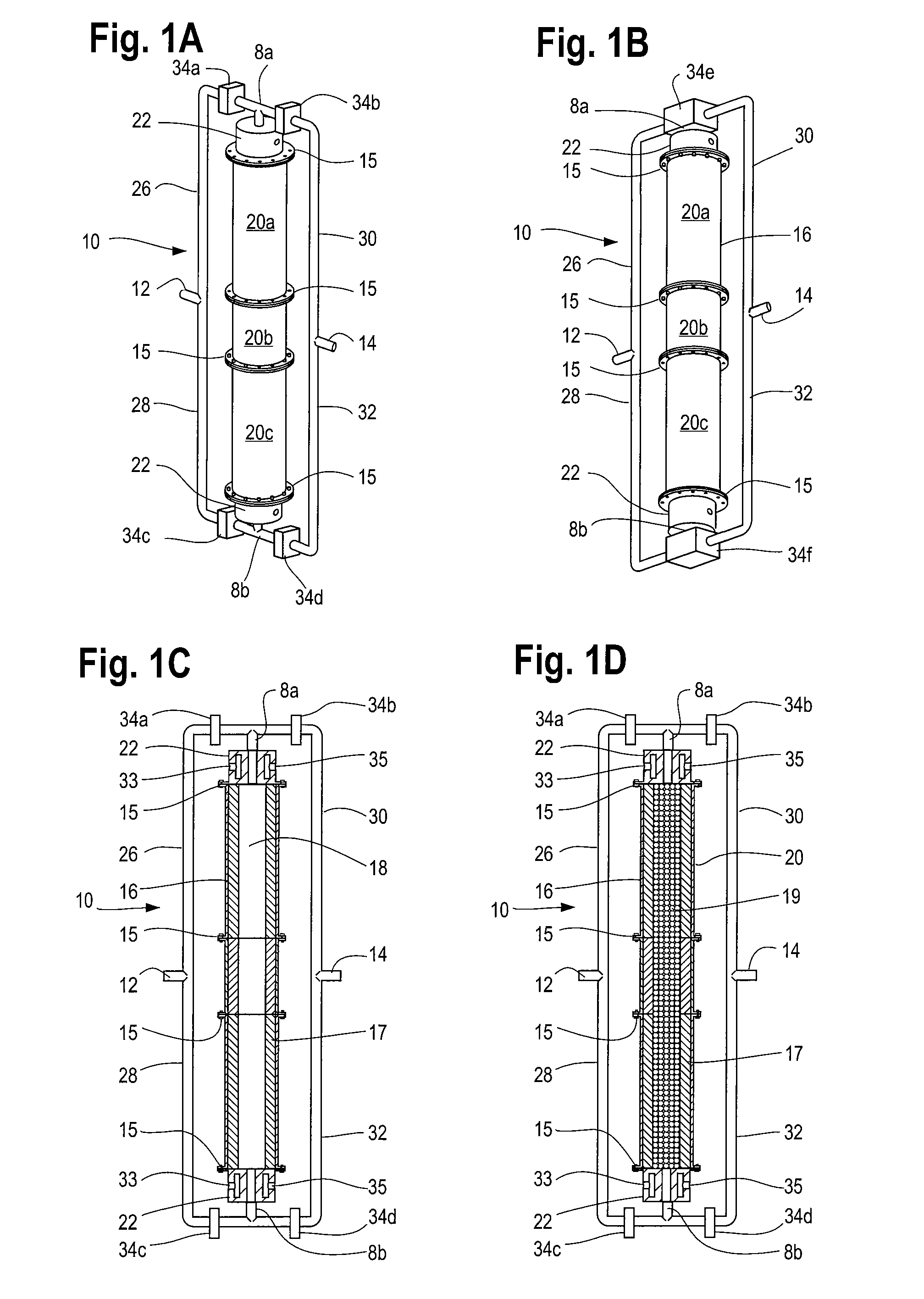
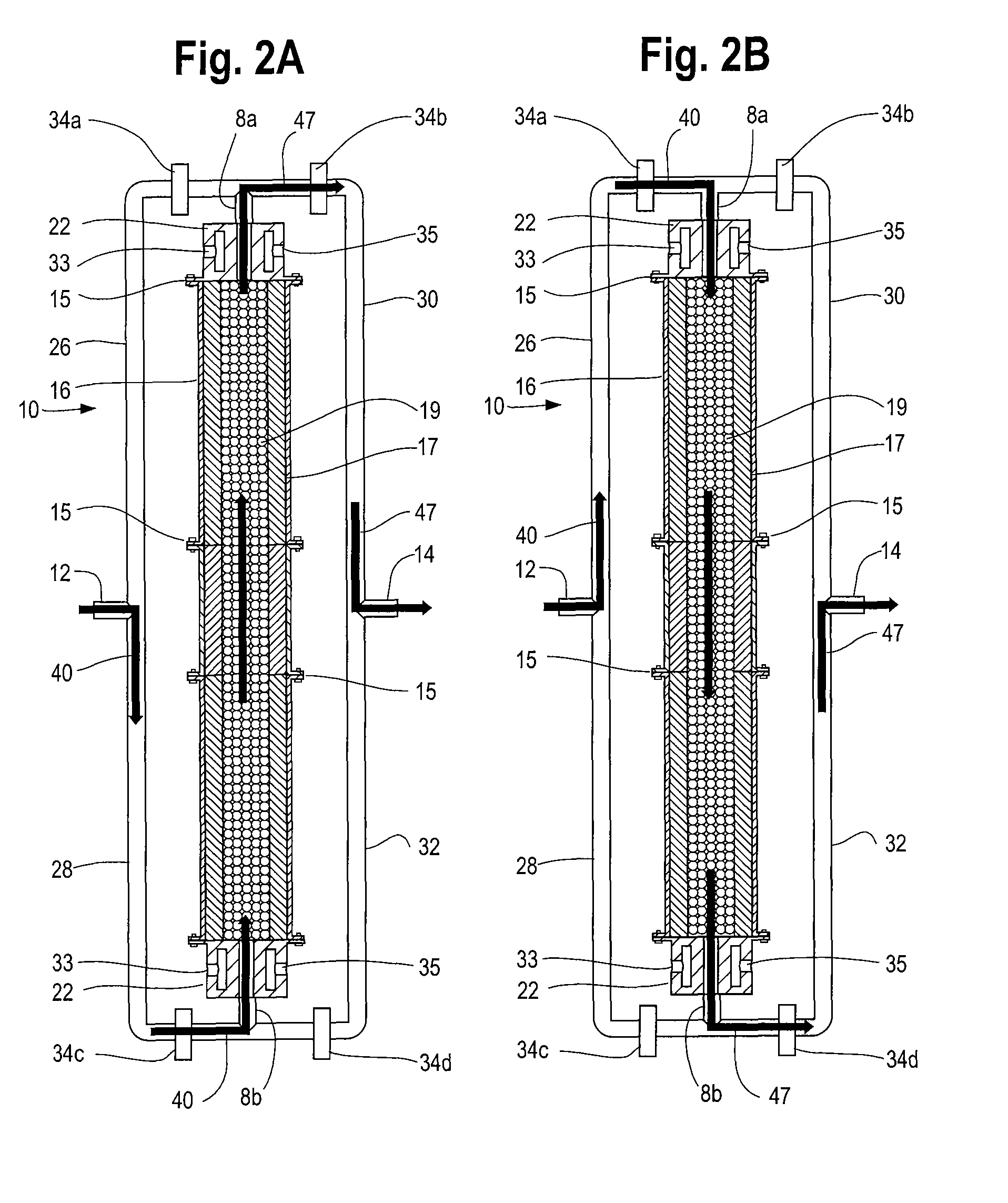
[0096]Another method of the process comprises reacting an ultra-rich mixture of H2S and an oxygen containing fluid inside the reactor 10 for the purpose of obtaining a product mixture 47 containing substantially pure hydrogen. The reformation of H2S to hydrogen and sulfur presents certain challenges not encountered in hydrocarbon reformation. For example, as H2S has a relatively low heat content compared to other possible fuels, obtaining a very high temperature in the partial oxidation regime is not likely. More importantly, H2S reforming requires the reaction to reach near equilibrium conditions at high temperature to obtain high yield. The intrinsic recuperating mechanism of the inert porous media matrix 19 and the reactor's ability to create an isothermal high temperature volume rendered it a cost effective option for the reformation of H2S by providing the necessary residence time and temperature.

[0097]For H2S reforming, the H2S concentration of the ...


PUM

PropertyMeasurementUnit
porosityaaaaaaaaaa
porosityaaaaaaaaaa
diameteraaaaaaaaaa

Abstract

The invention discloses an apparatus and process for the reformation of hydrogen containing fluids to hydrogen and other constituents, more particularly, the reformation of hydrocarbons or mixtures of hydrocarbons in a cyclic flow inert porous media reactor for the production of hydrogen and other constituents. In an alternate embodiment, the apparatus and process can be used for the reformation of hydrogen sulfide to produce hydrogen and sulfur.The cyclic flow reactor comprises a reaction chamber filled with a porous media matrix containing an unconstrained reaction zone located in any portion of the reactor chamber. This reactor system employs valves to canalize the reactant mixture and product mixture during flow cycling channeling the reactant mixture through the porous media matrix, and reacting the reactant mixture. In another embodiment, the reactor system may further comprise at least one aperture along the axial length of the reactor casing to enable mounting of an external energy source and / or at least one heat exchanger to provide a source of heat transfer to the inlet pipe and outlet pipe as well as the reactant mixture and product mixtures.

Description

FIELD OF THE INVENTION[0001]The invention discloses an apparatus and process for the reformation of hydrogen containing fluids to hydrogen and other constituents. More particularly, the invention is directed to the reformation of hydrocarbons or mixtures of hydrocarbons in a cyclic flow inert porous media reactor for the production of synthesis gas. In an alternate embodiment, the apparatus and process can be used for the reformation of hydrogen sulfide to produce hydrogen and sulfur.BACKGROUND OF THE INVENTION[0002]Hydrogen is an important feedstock in the manufacture of ammonia, methanol, and a variety of other chemicals; but its largest market is the crude oil processing industry. In crude oil refineries, hydrogen is used in a number of processes including hydrodesulfurization where hydrogen is reacted with sulfur containing compounds over a catalyst to form hydrogen sulfide. Hydrogen sulfide itself is already produced in great quantities during the drilling and processing of nat...

Claims


Application Information

Patent Timeline
Patent Type & Authority Patents(United States)
IPC IPC(8): B01J7/00B01J10/00C01B3/36C01B6/24
CPCB01J8/025B01J8/0221B01J8/001C01B3/48B01J19/0013B01J8/0285B01J8/0278C01B3/02C01B17/046C01B3/36B01J2208/0053B01J2208/00088C01B2203/1235C01B2203/0883B01J2208/025B01J2219/002B01J2219/00231B01J2208/00548B01J2208/00176B01J2219/00236C01B2203/0283C01B2203/0261C01B2203/042C01B2203/169C01B2203/0405C01B2203/0244C01B2203/04
Inventor BINGUE, JACQUES PICARDYWHITE, CHRISTOPHER LEEPIERRE-VICTOR, JEAN
Owner INNOVATIVE ENERGY SOLUTION
Learn More