Toner for developing electrostatic image, developer, image forming apparatus, process for forming image, process cartridge, and process for measuring porosity of toner

a technology toner cartridges, which is applied in the field of toner for developing electrostatic images, image forming apparatus, process for forming images, and process for measuring porosity of toner, can solve the problems of limited materials that can be used for toners, low yield, and still unsatisfactory levels of images created by full-color copiers, so as to improve the quality of toner. , the effect of improving the hollow

Active Publication Date: 2005-02-03
RICOH KK
View PDF84 Cites 91 Cited by
  • Summary
  • Abstract
  • Description
  • Claims
  • Application Information

AI Technical Summary

Benefits of technology

[0054] The toner for developing an electrostatic image includes at least a polyester resin, thus allowing resin's elasticity and degassing to better control the hollow state, which is more preferable.
[0055] The toner for developing an electrostatic image includes at least a modified polyester resin, thus allowing resin's elasticity and degassing to better control the hollow state, which can reinforce reduced toner hardness attributable to the presence of the pore, which is more preferable.
[0056] The toner for developing an electrostatic image with the particle having an average sphericity E of 0.90 to 0.99 can achieve further uniform degassing, thus making the hollow state more controllable and securing the toner hardness by the spherifying, which is more preferable.
[0057] The toner for developing an electrostatic image with the particle having a sphericity SF-1 of 100 to 150 and a sphericity SF-2 of 100 to 140 can achieve further uniform degassing, thus making th

Problems solved by technology

In general, for a user who is accustomed to commercial prints such as offset lithographic prints, images created by full-color copiers are still not at a satisfactory level, and demands are high for further improving the quality to achieve the fineness and resolution that are comparable to those of photographic and offset prints.
With pulverization, toners having somewhat favorable properties can be manufactured, but materials that can be used for the toners are limited.
The drawback is that the yield may become extremely low when one tries to obtain a reproduced image with favorable resolution and tone because a portion of the toner particles, for example, minute particulates of 5 μm or less in diameter and large grains of 20 μm or more, is to be removed by classification.
In addition, it is difficult in pulverization to evenly disperse a colorant, a charge control agent, and the like within a thermoplastic resin.
Uneven dispersion of the agents and additive may adversely affect the flowability, developability, durability, image quality, and the like of the toner.
However, toner particles manufactured by suspension polymerization have a drawback of poor cleanability although they are spherical.
However, when the toner coverage of an image is high, e.g. a photographic image, a paper jam or the like may result in building up of non-transferred residual toner on a photoconductor on which toner is forming an image but not transferred.
Accumulation of such residual toner leads to background shading.
Moreover, residual toner contaminates components such as a charging roller, which charges a photoconductor by contact charging, and subsequently reduces the charging performance of the charging roller.
Furthermore, concerns for toner particles formed by suspension polymerization include unsatisfactory fusibility at low temperatures and a large amount of energy required for fusion.
However, toner particles formed by emulsion polymerization have a large amount of residual surfactants inside the particles as well as on the surface thereof, even after being washed by water, which reduces the environmental stability of toner charge, increases the distribution of the amount of charge, and causes background shading on a printed image.
In addition, the residual surfactant contaminates photoconductor, charging roller, developing roller, and other components, thus causing problems such as insufficient charging performance.
However, this approach brings up an issue in which the method increases the lower limit fusing temperature at which toner is fused and therefore is unsatisfactory in low temperature fusibility, i.e. energy-saving fusion.
In addition, this process, in which

Method used


Image

  • Toner for developing electrostatic image, developer, image forming apparatus, process for forming image, process cartridge, and process for measuring porosity of toner
  • Toner for developing electrostatic image, developer, image forming apparatus, process for forming image, process cartridge, and process for measuring porosity of toner
  • Toner for developing electrostatic image, developer, image forming apparatus, process for forming image, process cartridge, and process for measuring porosity of toner

Examples


example 1

[0215] Manufacture Example 1 (Synthesis of Organic Particulate Emulsion)

[0216] To a reaction vessel provided with a stirrer and a thermometer, 683 parts of water, 11 parts of the sodium salt of the sulfuric acid ester of methacrylic acid ethylene oxide adduct (ELEMINOL RS-30, Sanyo Chemical Industries, Ltd.), 166 parts of methacrylic acid, 110 parts of butyl acrylate, and 1 part of ammonium persulphate were introduced, and stirred at 3800 rpm for 30 minutes to give a white emulsion. This was heated, the temperature in the system was raised to 75° C. and the reaction was performed for 4 hours. Next, 30 parts of an aqueous solution of 1% ammonium persulphate was added, and the reaction mixture was matured at 75° C. for 6 hours to obtain an aqueous dispersion of a vinyl resin “particulate emulsion 1” (copolymer of methacrylic acid-butyl acrylate-sodium salt of the sulfuric acid ester of methacrylic acid ethylene oxide adduct). The volume average particle diameter of “particulate emuls...

example 2

[0243] A toner is obtained in the same manner as that in Example 1 except that “pigment / wax dispersion 1” was changed to “pigment / wax dispersion 2” which was obtained by the following conditions for preparing the oil phase.

[0244] (Preparation of Oil Phase)

[0245] Into a vessel equipped with a stirrer and a thermometer, 378 parts of “low molecular weight polyester 1,” 100 parts of carnauba / rice wax (weight ratio of carnauba to rice is 7 to 3), and 947 parts of ethyl acetate were introduced, and the temperature was raised to 80° C. with stirring, maintained at 80° C. for 4 hours, and cooled to 30° C. in 1 hour. Next, 500 parts of “masterbatch 1” and 500 parts of ethyl acetate were introduced into the vessel, and mixed for 1 hour to obtain “initial material solution 2.”

[0246] To a vessel, 1324 parts of “initial material solution 2” were transferred, and carbon black and wax were dispersed using a bead mill (ultra bead mill available from Imex) under the conditions of liquid feed rate ...

example 3

[0249] A toner is obtained in the same manner as that in Example 1 except that the processes of emulsification and solvent removal were changed to have conditions as described below.

[0250] (Emulsification and Solvent Removal)

[0251] In a vessel, 749 parts of “pigment / wax dispersion 1,” 115 parts of “prepolymer 1” and 2.9 parts of “ketimine compound 1” were placed and mixed at 5,000 rpm for 2 minutes by a TK homomixer (available from Tokushu Kika Kogyo Co., Ltd.), then 1200 parts of “aqueous phase 1” were added to the vessel and mixed by the TK homomixer at a rotation speed of 13,000 rpm for 10 minutes to obtain “emulsion slurry 3.”

[0252]“Emulsion slurry 3” was placed in a vessel equipped with a stirrer and a thermometer, then the solvent was removed at 30° C. for 6 hours and the product was matured at 45° C. for 10 hours to obtain “dispersion slurry 3.”

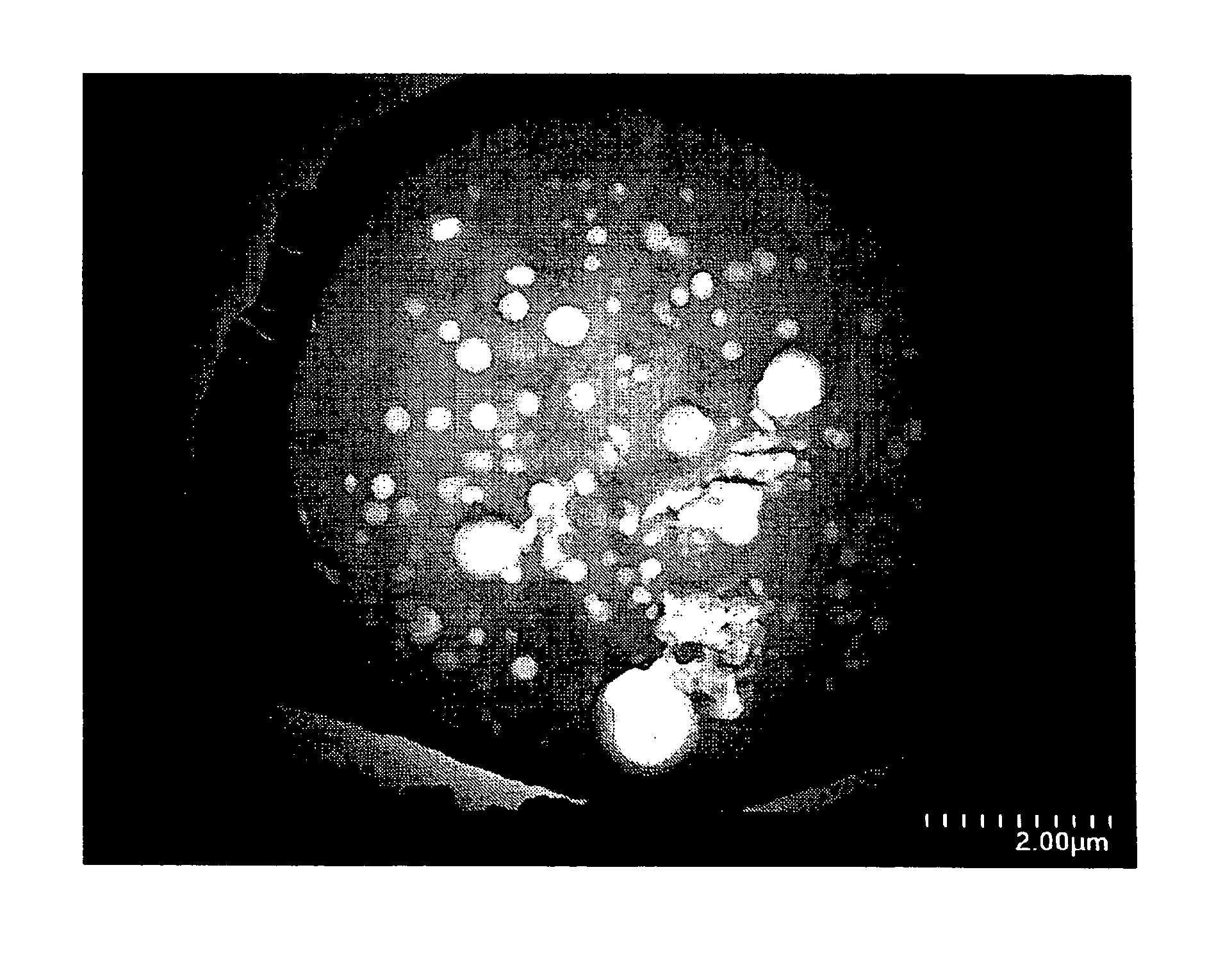
[0253] Like Example 1, a cross section of the thus obtained toner particle was prepared and observed. Like Example 1, at least one ...


PUM

PropertyMeasurementUnit
Thicknessaaaaaaaaaa
Thicknessaaaaaaaaaa
Diameteraaaaaaaaaa

Abstract

A toner for developing an electrostatic image, includes: a colorant; and a binder resin. The toner has a particle including at least one pore having a diameter of 10 nm or over, and a porosity thereof is in a range from 0.01 to 0.60.

Description

BACKGROUND OF THE INVENTION [0001] 1. Field of the Invention [0002] The present invention relates to a toner for developing an electrostatic image, a developer, an image forming apparatus, a process for forming an image, a process cartridge, and a process for measuring porosity of the toner. [0003] 1. Description of the Related Art [0004] In an electrophotographic device, an electrostatic recording device or the like, an electrostatic latent image is formed on a photoconductor, to which a toner is attracted. The toner is transferred to a transfer material, such as a sheet of paper, and then fused to the transfer material by heat and thus a toner image is formed. To form a full-color image, it is generally done by using four toners of different colors consisting of black, yellow, magenta, and cyan. Development is carried out for each color, each layer of toner is overlaid on the transfer material to form the toner image, and the toner image is then heated and simultaneously fused to ...

Claims


Application Information

Patent Timeline
IPC IPC(8): G03G9/08G03G9/087
CPCG03G9/0806G03G9/0819G03G9/08797G03G9/08764G03G9/08795G03G9/0827
Inventor SUGIURA, HIDEKIMOCHIZUKI, SATOSHIIWAMOTO, YASUAKIASAHINA, YASUOKOTSUGAI, AKIHIRONAKAYAMA, SHINYAICHIKAWA, TOMOYUKISAKATA, KOICHIUTSUMI, TOMOKONAKAJIMA, HISASHI
Owner RICOH KK
Why Eureka
Try Eureka