In face-to-face communication, acoustic background noise disturbs a listener and makes it more difficult to understand speech.
In the case of
telephony, background noise is troublesome because there is no additional information provided by facial expressions and gestures.
In digital
telephony, the deleterious effect of background noise can be great.
This is due to the fact that speech codecs are generally optimised for efficient compression and acceptable reconstruction of speech and their performance can be impaired if noise is present in the speech signal, or errors occur in speech transmission or reception.
In addition, the presence of noise itself can lead to
distortion to the background noise signal when it is encoded and transmitted.
Impaired performance of a speech codec reduces both the intelligibility of the transmitted speech and its
subjective quality.
Distortion of the transmitted background noise signal degrades the quality of the transmitted signal, making it more annoying to listen to and rendering
contextual information less recognisable by changing the nature of the background noise signal.
The problems discussed above relate to arrangements in which only one
microphone is present to provide only one signal.
However, in noisy conditions the performance of the speech decoder may be affected detrimentally, resulting in one or more of the following effects: 1.
The background noise may sound unnatural because codecs are generally optimised for compressing speech rather than noise.
Typically this gives rise to increased periodicity in the background
noise component and may be sufficiently severe to cause the loss of
contextual information carried by the background noise signal.
Information about an encoded speech signal may also be lost or corrupted during transmission and reception, for example due to
transmission channel errors.
This situation may give rise to further deterioration in the speech decoder output, causing additional artefacts to become apparent in the decoded speech signal.
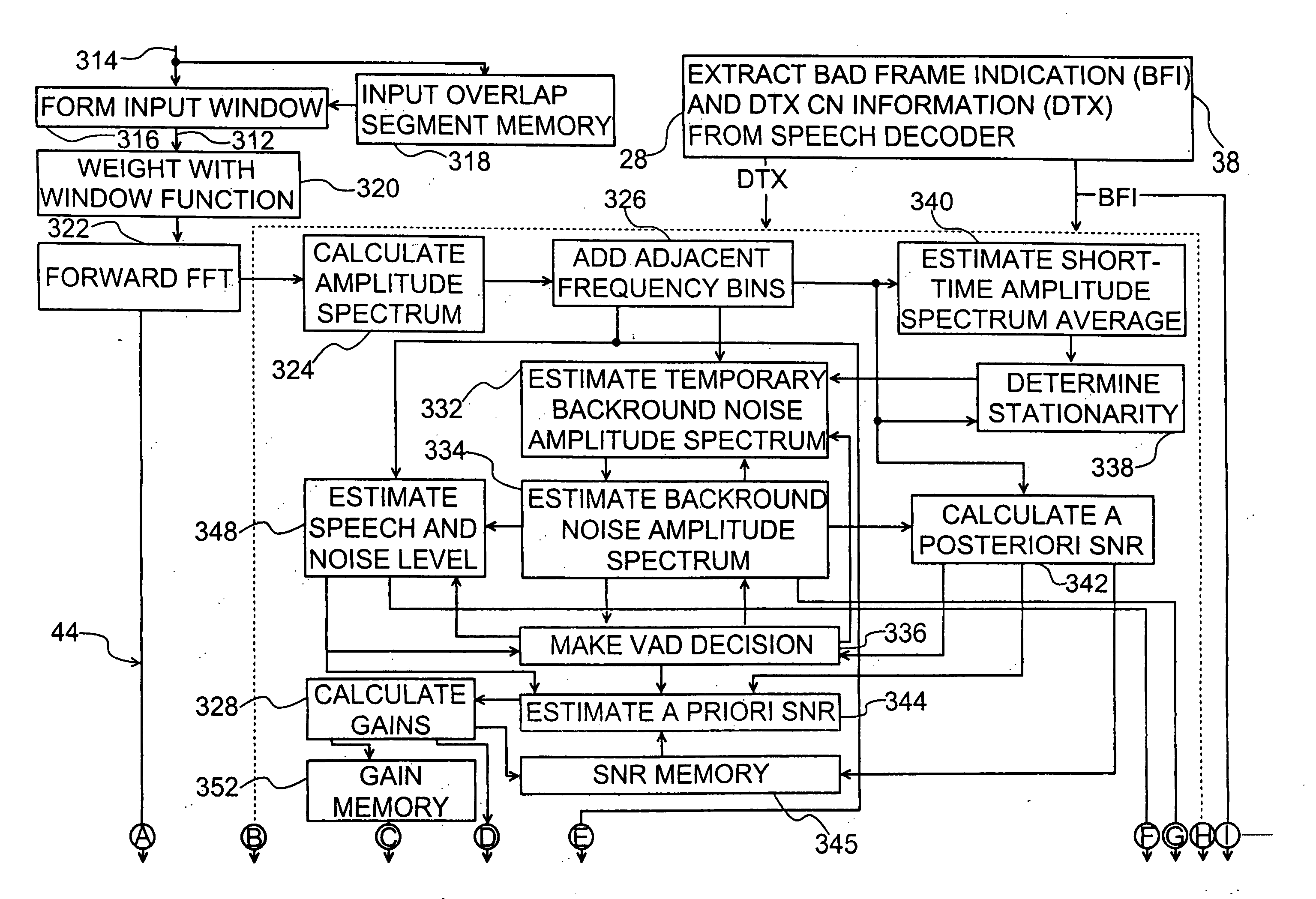
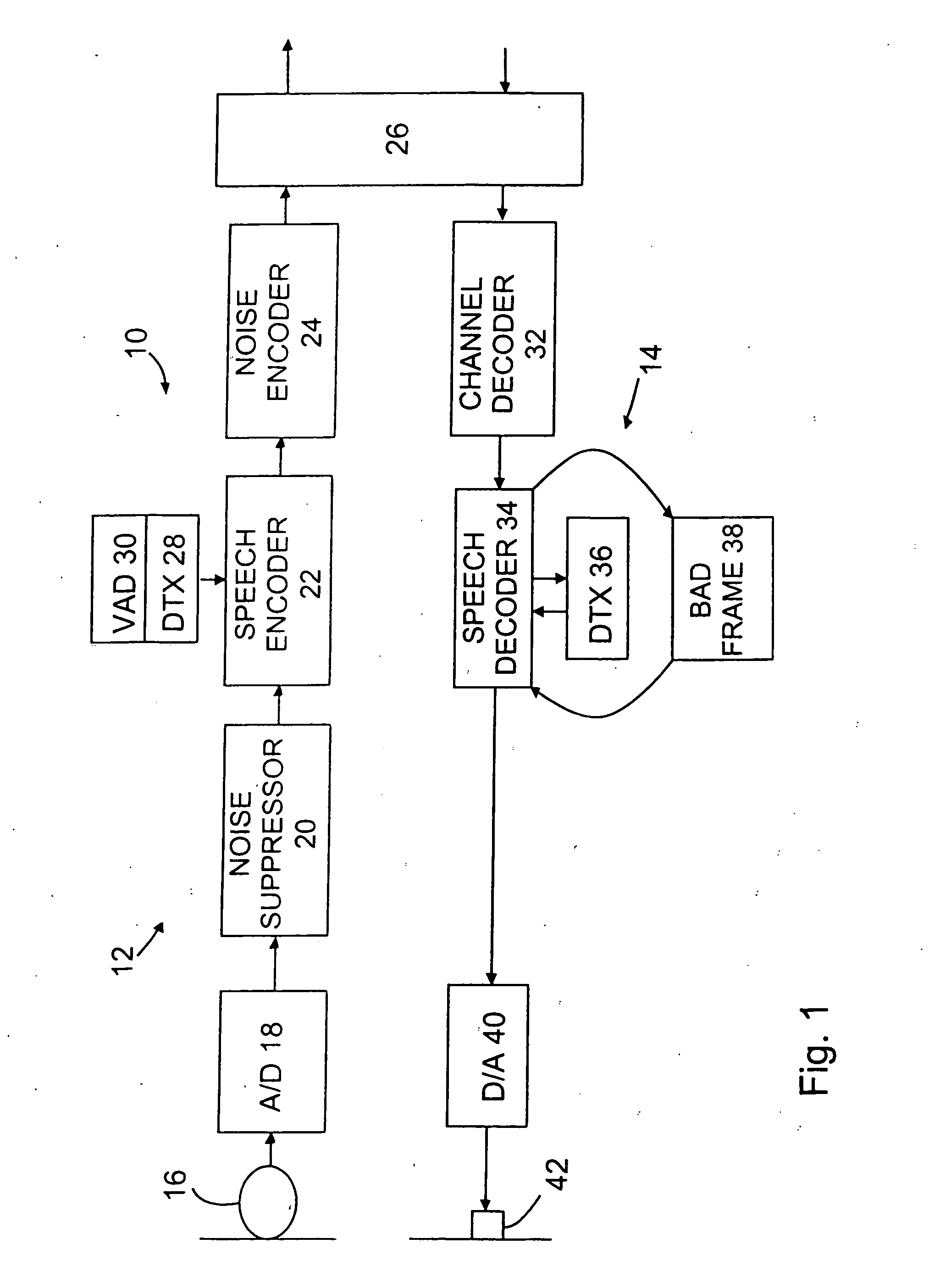
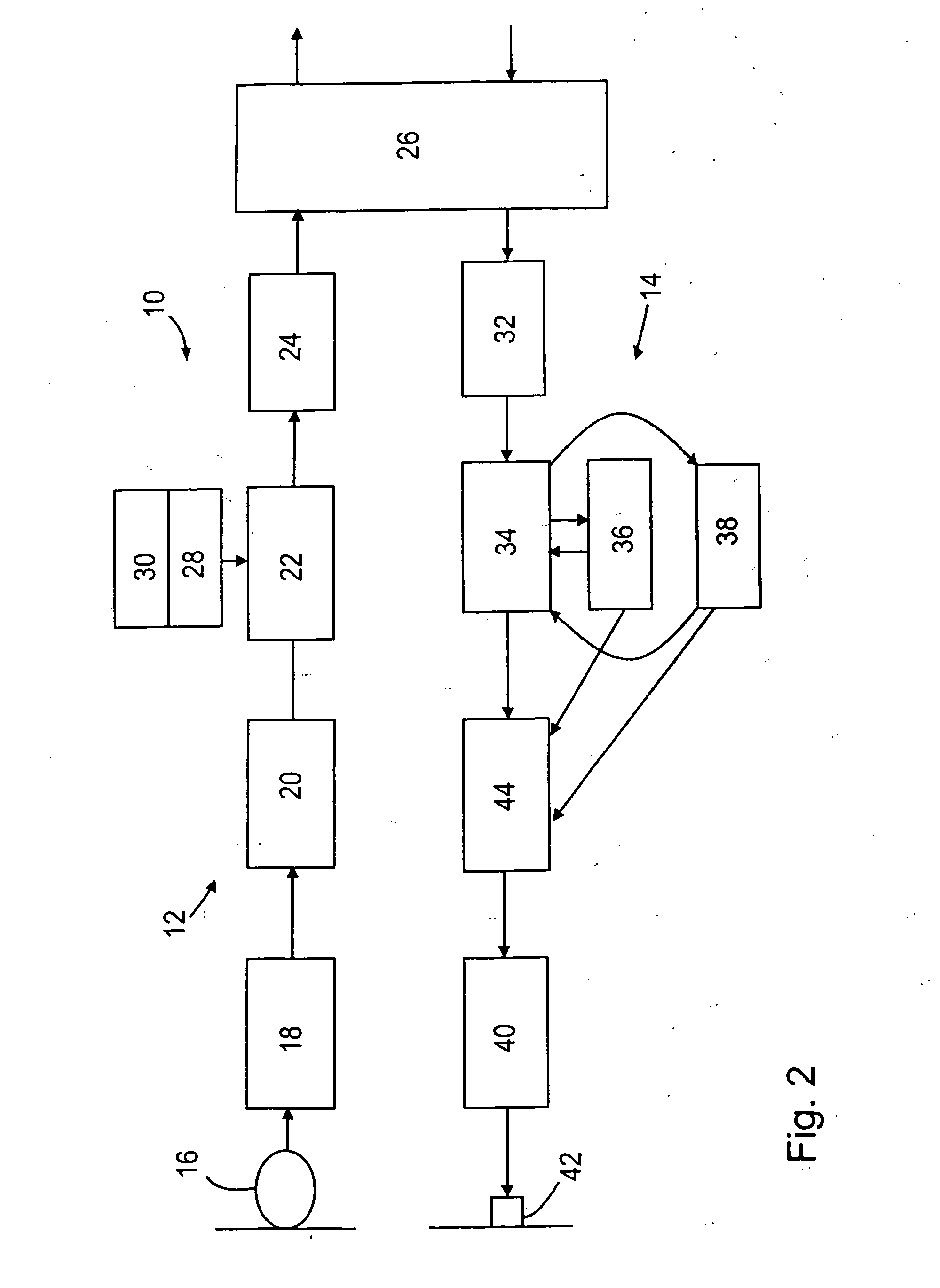
When a noise suppressor is used in the speech decoding path, after a speech decoder, non-optimal performance of the speech decoder may in turn cause the noise suppressor to operate in a less than optimal manner.
However, due to the intrinsic properties of typical speech codecs, which are optimised for the encoding and decoding of speech, decoded background noise can sound more annoying than the original noise signal and so it should be attenuated as much as possible.
The most significant difficulty in detecting speech in a signal generated by a mobile terminal is that the environments in which such terminals are used often lead to low speech / noise ratios.
The noise levels in environments where mobile terminals are used may change constantly.
Of course, it is not prudent for the VAD 30 to up-date these values on the basis of its own decision about the presence of speech.
In most
mobile telecommunication systems, DTX is mostly applied in the up-link connection since speech encoding and transmission is typically much more power consuming than reception and speech decoding, and because the mobile terminal typically relies on the limited energy stored in its battery.
Furthermore, in a mobile-to-mobile connection, no information is provided in the down-link connection about the occurrence of DTX in the up-link connection.
If errors occur in the
transmission channel, normal decoding of lost or erroneous speech frames would give rise to a listener hearing unpleasant noises.
This substitution provides continuity of the speech signal and is accompanied by a gradual attenuation of the output level, resulting in silencing of the output within a rather short period.
However, substitution and attenuation of the usually uninformative background noise in the lost frames affects the perceived quality of the noisy speech or the pure background noise.
Even at rather low levels of background noise, rapid attenuation of the background noise in lost frames leads to an impression of a badly decreased fluency of the transmitted signal.

