Multi-hop peer-to-peer wireless local loop phone system and method

a wireless local loop and phone system technology, applied in the field of peer-to-peer wireless local loop phone system, can solve the problems of expensive towers that must be installed to provide coverage for the geographic area, towers that must provide enough connections for all local phone calls, and the need for phone service, so as to minimize the number of hops, minimize the latency added, and maximize the throughput around the gateway

Inactive Publication Date: 2005-02-17
CALVERT NATHAN HUNTER
View PDF5 Cites 74 Cited by
  • Summary
  • Abstract
  • Description
  • Claims
  • Application Information

AI Technical Summary

Benefits of technology

[0009] The system of relaying calls through a combination of hops between the units creates a powerful network with low latency (voice delay / quality) levels. The local network requires no wire lines or central switching centers (although their existence by no means precludes the present invention's technology) to cover the geographical area or to make local calls. The need for only a single interconnection point to link the local peer network to the PSTN provides significant infrastructure installation savings over traditional wireline telephone services. The leveraging of local peer networks onto PSTN's via single interconnection points substantially reduces capital costs and allows Telcos the ability to affordably extend service to previously unreachable markets
[0012] The present invention also comprises network configuration algorithms by which a virtual circuit data path is established by minimizing the latency added at each hop starting with the external network gateway or the most loaded hop and choosing closest time slots for each next hop until a the virtual circuit is completed.
[0013] Also, certain embodiments of the present invention include network configuration algorithms by which traffic around any external network gateway(s) is optimized to maximize throughput around the gateway by allocating certain of many available channels to a group of P2P units around the gateway, these units acting as an “infrastructure” through which other units route virtual circuits through the gateway. The network topology is also configured to let these units transmit at higher power levels and ranges than other P2P units in the network, and thereby help minimize the number of hops needed to reach the external network gateway. Further, other sets of units can be configured with similar larger transmit ranges (around 4 of the standard P2P hop ranges), positioned at such a range on the opposite side of from the gateway to also act as “infrastructure units”, both to pass calls forward to the group of units in the gateway's Point Coordinator group, and to also route circuits that are internal to the network around the Point Coordinator group on the gateway, thereby maximizing efficient use of the gateway capacity. Such rings or layers of infrastructure can be repeated as necessary to minimize hops as the network grows larger, making the tradeoff between minimizing hops (which maximizes transmit power and increases co-channel interference) and minimizing power (which maximizes the number of hops and produces poor latency).

Problems solved by technology

However, using centralized “cellular” wireless local loop has the drawback that expensive towers must be installed to provide coverage for the geographic area to which local loop phone service is provided.
Another disadvantage of the cellular approach is that the towers must provide enough connections for all local phone calls as well as calls leaving the network.
In many areas, the local phone service is a large majority of the phone traffic available, so the necessity for centrally switching local phone calls in either a wired or wireless system adds enormous costs to the network.
Such prior art systems have, however, been designed for broadband data traffic and battlefield multicast command and control applications, and have not been optimized for the strict latency requirements of telephone voice traffic.
Further, the media access control portions of these interfaces have not been optimized to minimize latency or maximize the scalability of the network to accommodate a system that provides the cheapest possible coverage by minimizing the number of external network gateways needed to provide coverage to a large population.
A further disadvantage of the prior art peer-to-peer wireless systems is that their multiple access (wireless terminology) or media access control (networking terminology) is not optimized to provide access to the available wireless channel(s) to minimize latency while at the same time minimizing co-channel interference from other simultaneously transmitting peers in the network.
Finally, the prior art systems also are not designed to optimize the above described performance parameters while at the same time maximizing throughput to the critically loaded external network gateway to maximize the efficiency of the external network gateway and thereby help minimize total connectivity cost of the system.

Method used


Image

  • Multi-hop peer-to-peer wireless local loop phone system and method
  • Multi-hop peer-to-peer wireless local loop phone system and method
  • Multi-hop peer-to-peer wireless local loop phone system and method

Examples


Embodiment Construction

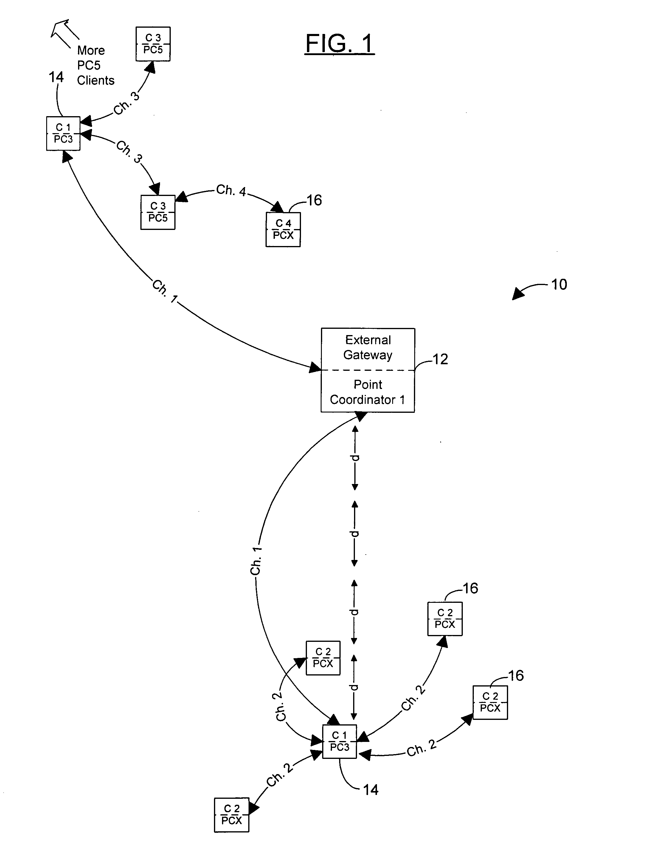
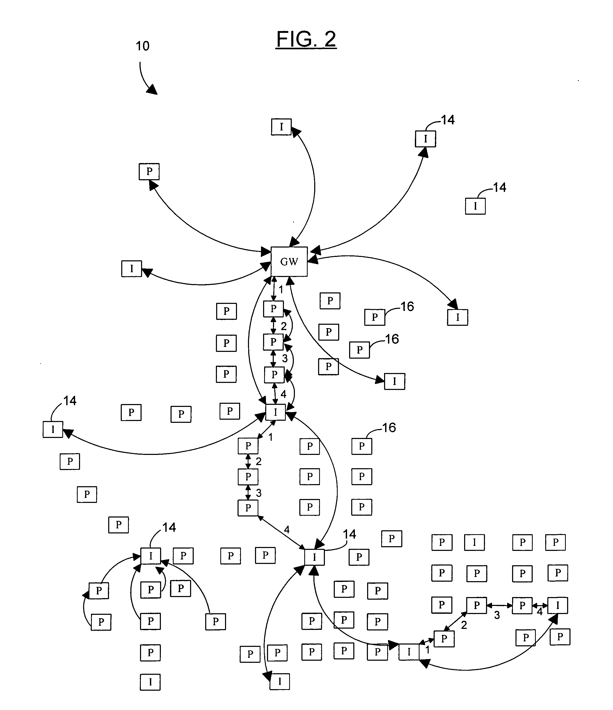
[0027] Referring now to the drawings, and particularly to FIGS. 1-2, a preferred embodiment of the peer-to-peer wireless local loop phone system of the present invention is shown and generally designated by the reference numeral 10.

[0028] In FIG. 1, a new and improved peer-to-peer wireless local loop phone system 10 of the present invention for providing local phone service without the use phone lines or central base stations with a peer-to-peer multi-hop wireless phone terminal is illustrated and will be described, with only the central portion of the network shown. More particularly, the peer-to-peer wireless local loop phone system 10 has a unit 12 external gateway connected to the PSTN or to the internet or other backbone gateway of some kind. Next the system 10 is comprised of peer-to-peer (P2P) units, which are not homogenous in their function, but take on different roles. The Gateway 12 connects to the infrastructure units 14 by radio transceivers, and the infrastructure uni...


PUM


Abstract

A peer-to-peer wireless phone system with peer-to-peer units and network configuration algorithms by which a virtual circuit data path is established by minimizing the latency added at each hop starting with the external network gateway or the most loaded hop and choosing closest time slots for each next hop until a the virtual circuit is completed. Also, certain embodiments of the present invention include network configuration algorithms by which traffic around any external network gateway(s) is optimized to maximize throughput around the gateway by allocating certain of many available channels to a group of P2P units around the gateway, these units acting as an “infrastructure” through which other units route virtual circuits through the gateway. The network topology is also configured to let these units transmit at higher power levels and ranges than other P2P units in the network, and thereby help minimize the number of hops needed to reach the external network gateway. Further, other sets of units can be configured with similar larger transmit ranges (around 4 of the standard P2P hop ranges), positioned at such a range on the opposite side of from the gateway to also act as “infrastructure units”, both to pass calls forward to the group of units in the gateway's Point Coordinator group, and to also route circuits that are internal to the network around the Point Coordinator group on the gateway, thereby maximizing efficient use of the gateway capacity. Such rings or layers of infrastructure can be repeated as necessary to minimize hops as the network grows larger, making the tradeoff between minimizing hops (which maximizes transmit power and increases co-channel interference) and minimizing power (which maximizes the number of hops and produces poor latency).

Description

CROSS REFERENCE TO RELATED APPLICATIONS [0001] This application claims the benefit of provisional application No. 60 / 492,454, filed Aug. 4, 2003, pending and provisional application No. 60 / 553,691, filed Mar. 16, 2004, pending. BACKGROUND OF THE INVENTION [0002] 1. Field of the Invention [0003] The present invention relates to a peer-to-peer wireless local loop phone system for use in connection with providing low cost basic telecommunications service to customers. The peer-to-peer wireless local loop phone system has particular utility in connection with providing local phone service without the use phone lines or central base stations with a peer-to-peer multi-hop wireless phone terminal. [0004] 2. Description of the Prior Art [0005] Wireless local loop phone systems are desirable connecting local phone subscribers to the PSTN and other data networks without the use of copper wires for the “last mile” connection. However, using centralized “cellular” wireless local loop has the dr...

Claims


Application Information

Patent Timeline
Patent Type & Authority Applications(United States)
IPC IPC(8): H04L12/28H04L12/56H04W40/02H04W40/22H04W40/24H04W40/26H04W72/04H04W76/02H04W84/14H04W92/18
CPCH04L45/00H04W28/26H04W40/02H04W40/22H04W40/246Y02B60/50H04W72/04H04W76/023H04W84/14H04W92/18H04W40/26H04W76/14Y02D30/00Y02D30/70
Inventor CALVERT, NATHAN HUNTER
Owner CALVERT NATHAN HUNTER
Why Eureka
Try Eureka