Multi-pair gigabit ethernet transceiver

Inactive Publication Date: 2005-02-17
AVAGO TECH INT SALES PTE LTD
View PDF1 Cites 19 Cited by
  • Summary
  • Abstract
  • Description
  • Claims
  • Application Information

AI Technical Summary

Benefits of technology

The present invention further provides a method for reducing system performance degradation caused by switching noise in a system which includes a set of subsystems. Each of the subsystems includes an analog section and a digital section. Each of the analog sections operates in accordance with a corresponding one of a set of sampling clock signals which are synchronous in frequency. The digital sections opera

Problems solved by technology

However, as the need to exchange information becomes more and more imperative, and as the scope and size of the information being exchanged increases, higher and higher speeds (greater bandwidth) are required from network interconnect technologies.
Simultaneous, parallel transmission of four information signals over four twisted wire pairs poses substantial challenges to bidirectional communication transceivers, even though the data rate on any one wire pair is “only” 250 Mbps.
Thus, demodulator/decoder architectures must be implemented with a degree of computational complexity that allows them to accommodate not only the “state width” of Trellis coded signals, but also the “dimensional depth” represented by the transmission channel.
A perhaps greater challenge is that the complex computations required to process “deep” and “wide” signal representations must be performed in an almost vanishingly small period of time.
If performed in conventional fashion, sequential signal processing operations necessary for signal decoding and demodulation would result in a propagation delay through the logic circuits that would exceed the clock period, rendering the transceiver circuit non-functional.
Wi

Method used


Image

  • Multi-pair gigabit ethernet transceiver
  • Multi-pair gigabit ethernet transceiver
  • Multi-pair gigabit ethernet transceiver

Examples


first embodiment

The absolute values of the active tap coefficients are compared with the threshold (block 3010). The taps whose absolute values are less than the threshold are deactivated (block 3012). An error metric, typically a mean squared error (MSE) corresponding to a ratio of mean squared error to signal, and a power metric are computed (block 3014). Process 3000 then checks whether a first test is satisfied (block 3016). In the invention, this first test is satisfied when the error metric is greater than the specified error and the power metric is smaller than the specified maximum power. If the error metric is greater than the specified error, this implies that the threshold has been set too high, causing too many taps to be deactivated, and this has degraded the system performance by more than the specified amount. If the first test is satisfied, then the threshold is decreased (block 3018), and all the taps in the block being considered are activated again (block 3006) and process 3000 p...

third embodiment

In the present invention, the first few taps of each filter, e.g., the first 10 taps, are exempt from deactivation in order to avoid possible degradations of the system performance in the presence of jitter. The effect of jitter on these few taps is as follows. There is usually a large slew rate in these first few taps. Due to this slew rate, their numerical values could change significantly if the sampling phase of the received signal changes. In the presence of jitter, the sampling phase of the received signal can change dynamically. Thus, if some of the first few taps were insignificant for the system performance, they could become significant as the sampling phase changes. For this third embodiment, the flowchart of the deactivation process of block 3012 is slightly different from the one shown in FIG. 30. The only modification to the flowchart of FIG. 30 is to equate, in block 3006, the address to K instead of 0, where K+1 is the number of the first few taps exempt from deactiv...

fourth embodiment

the present invention uses, as the error metric, the change in the true MSE instead of the true MSE. In other words, the value of {new (true MSE) B old (true MSE)} is computed and used as the error metric. In the fourth embodiment, the first test in block 3016 is satisfied if the change in the true MSE is greater than a specified change value (e.g., a value that corresponds to a noise to signal ratio (NSR) change of 1 dB) and the power metric is smaller than the specified maximum power. The second test in block 3024 is satisfied if the change in the true MSE is smaller than the specified change value or the power metric is greater than the specified maximum power. For example, if the true MSE is at a value corresponding to a NSR of B25 dB before the tap power regulating process is applied, and if the specified change value corresponds to a NSR change of 1 dB, then the final true MSE will be at a value corresponding a NSR of about B24 dB. This fourth embodiment can be used when there...


PUM


Abstract

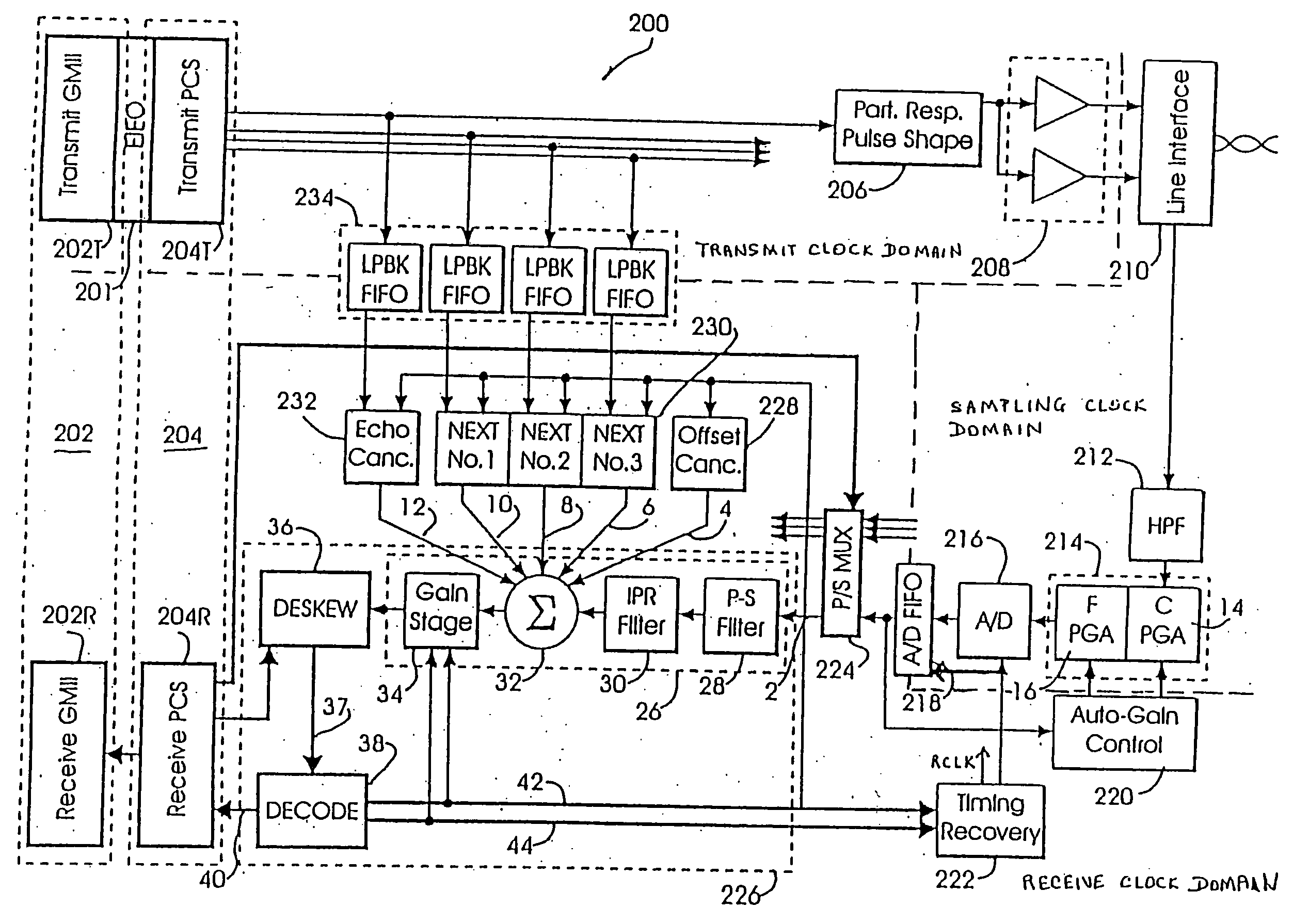
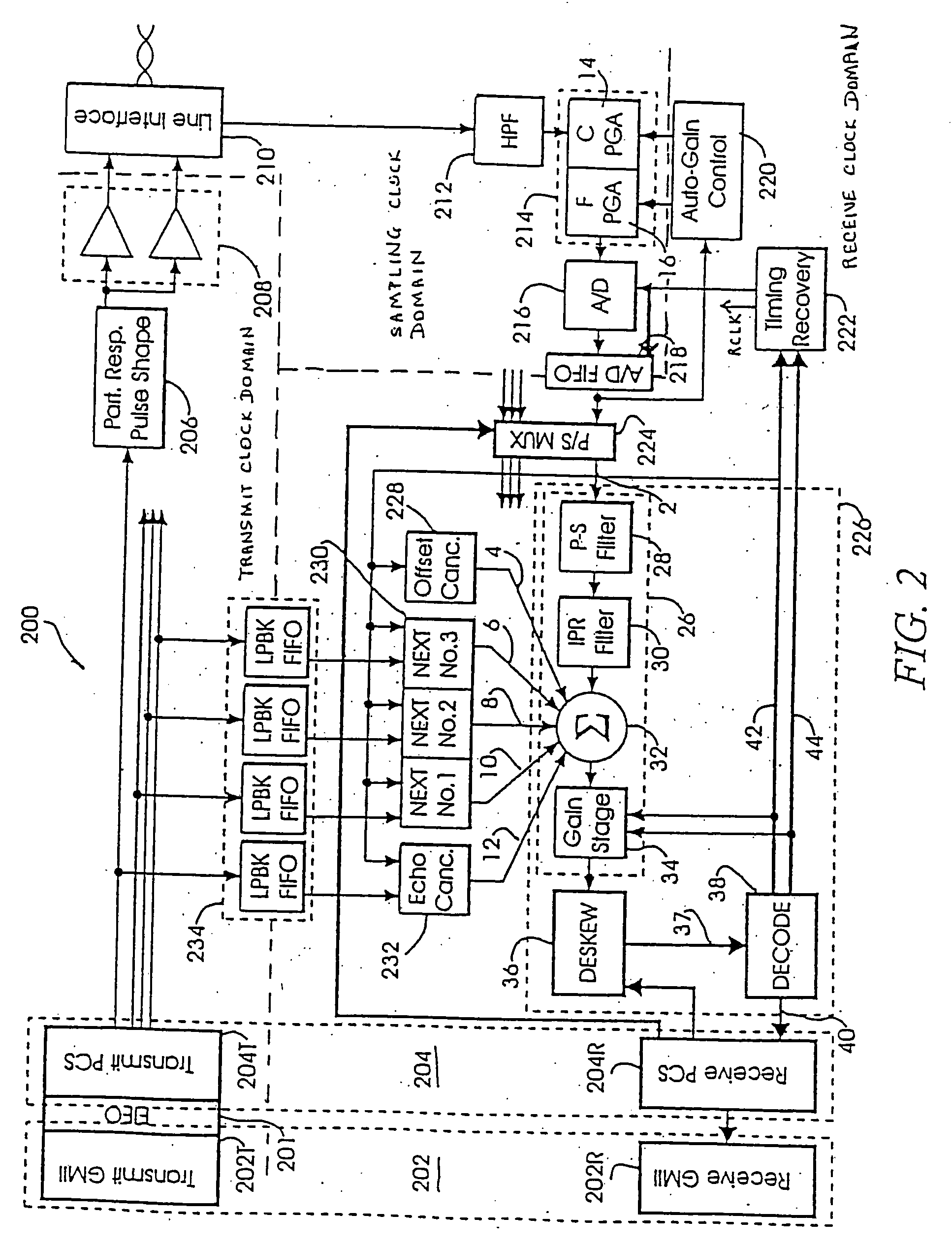
Various systems and methods providing high speed decoding, enhanced power reduction and clock domain partitioning for a multi-pair gigabit Ethernet transceiver are disclosed. ISI compensation is partitioned into two stages; a first stage compensates ISI components induced by characteristics of a transmitters partial response pulse shaping filter in a demodulator, a second stage compensates ISI components induced by characteristics of a multi-pair transmission channel in a Viterbi decoder. High speed decoding is accomplished by reducing the DFE depth by providing an input signal from a multiple decision feedback equalizer to the Viterbi based on a tail value and a subset of coefficient values received from a unit depth decision-feedback equalizer. Power reduction is accomplished by adaptively truncating active taps in the NEXT, FEXT and echo cancellation filters, or by disabling decoder circuitry portions, as channel response characteristics allow. A receive clock signal is generated such that it is synchronous in frequency with analog sampling clock signals and has a particular phase offset with respect to one of the sampling clock signals. This phase offset is adjusted such that system performance degradation due to coupling of switching noise from the digital sections to the analog sections is substantially minimized.

Description

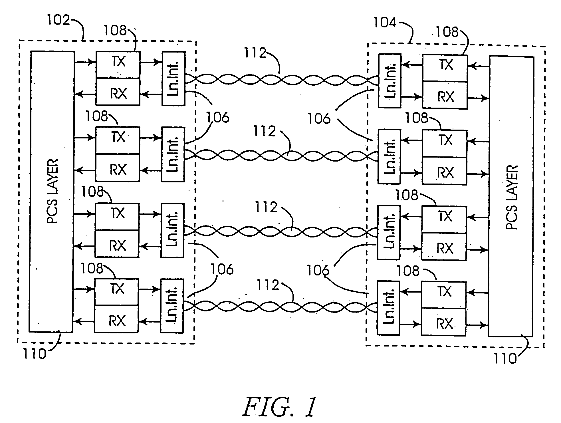
FIELD OF THE INVENTION The present invention relates generally to high speed networking transceivers and, more particularly to gigabit Ethernet transceivers having reduced power consumption, efficient clock domain partitioning and able to decode input symbols within a symbol period with a minimum of computational intensity. DESCRIPTION OF THE RELATED ART In recent years, local area network (LAN) applications have become more and more prevalent as a means for providing local interconnect between personal computer systems, work stations and servers. Because, of the breadth of its installed base, the 10BASE-T implementation of Ethernet remains the most pervasive if not the dominant, network technology for LANs. However, as the need to exchange information becomes more and more imperative, and as the scope and size of the information being exchanged increases, higher and higher speeds (greater bandwidth) are required from network interconnect technologies. Among the highspeed LAN tech...

Claims


Application Information

Patent Timeline
IPC IPC(8): G01R31/30G01R31/317G01R31/3185H04B3/23H04B3/32H04L1/00H04L1/24H04L5/14H04L7/02H04L7/033H04L25/03H04L25/06H04L25/14H04L25/49H04L25/497
CPCG01R31/3004H04L2025/03745G01R31/3016G01R31/31715G01R31/318502G01R31/318552G01R31/318594H04B3/23H04B3/235H04B3/32H04L1/0021H04L1/0047H04L1/0053H04L1/0054H04L1/0059H04L1/006H04L1/242H04L5/14H04L7/0062H04L7/0334H04L25/03038H04L25/03057H04L25/03146H04L25/03197H04L25/03203H04L25/03235H04L25/03267H04L25/03987H04L25/067H04L25/14H04L25/4917H04L25/497H04L2001/0096H04L2025/03363H04L2025/03369H04L2025/03477H04L2025/0349H04L2025/03496H04L2025/03503H04L2025/03617G01R31/3008
Inventor AGAZZI, OSCAR E.CREIGH, JOHN L.HATAMIAN, MEHDISAMUELI, HENRYKRUSE, DAVID E.ABNOUS, ARTHUR
Owner AVAGO TECH INT SALES PTE LTD
Why Eureka
Try Eureka