

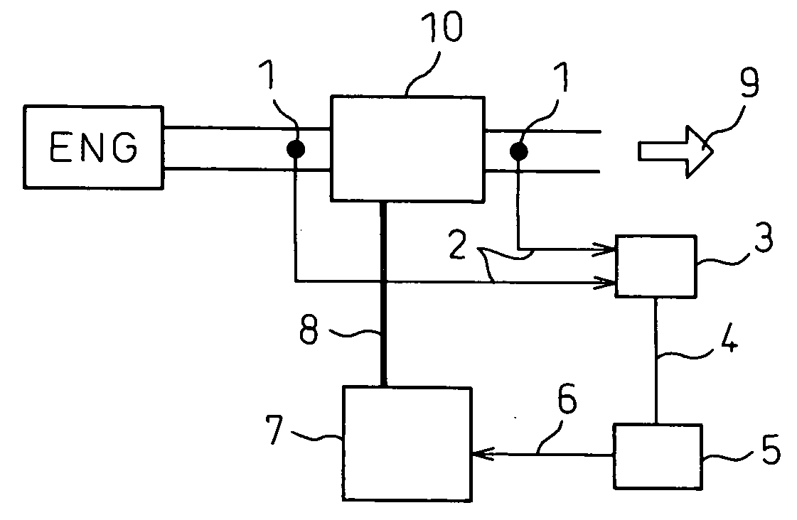
Exhaust gas purifying apparatus
a technology of exhaust gas purification and purification apparatus, which is applied in the direction of machine/engine, exhaust treatment electric control, separation process, etc., can solve the problems of large amount of pm accumulated in the dpf, unstable plasma generation, and large load on the engine, so as to improve the trapping effect of pm
- Summary
- Abstract
- Description
- Claims
- Application Information
AI Technical Summary
Benefits of technology
Problems solved by technology
Method used
Image

Examples
example 1
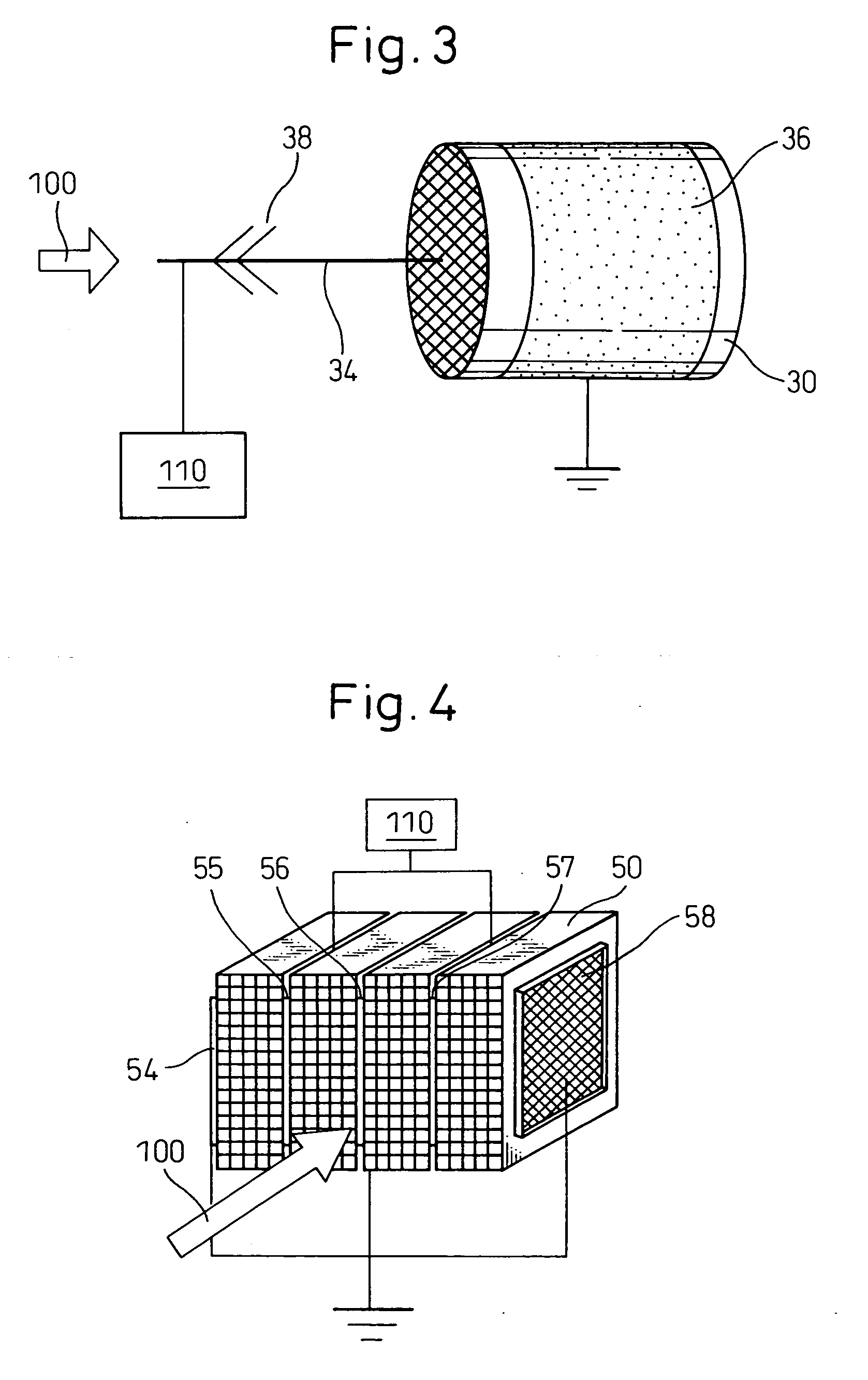
[0050] A PM purifying reactor was provided as shown in FIG. 3. That is, in this reactor, around the circumference surface of a straight-flow type cordierite honeycomb structure (diameter: 30 mm and length: 50 mm, cell density: 200 cells / square inch, porosity: 65%, and average pore size: 25 μm (micro meters)), a stainless steel mesh (width: 40 mm, SUS 304, 300 mesh) was surrounded to be an outer electrode. On the center axis of the honeycomb structure, a center electrode (bar electrode) having needle electrodes was fixed.
example 2
[0051] The exhaust gas purifying apparatus of this example was the same as that of the example 1, except that a wall-flow type cordierite honeycomb structure (cell density: 300 cells / square inch, porosity: 65%, and average pore size: 25 μm) was used in place of the straight-flow type cordierite honeycomb of the example 1.
[0052] Performance Evaluation: PM trapping
[0053] Each of the reactors of the examples 1 and 2 was surrounded by an alumina mat and inserted in a quartz tube having an inner diameter of 37 mm (milli-meters). The center electrode was electrically connected to an electric power supply, and the outer electrode was grounded. To the exhaust gas purifying apparatus, a part of the exhaust gas (100 L / minute) from a direct-injection system diesel engine having a displacement volume of 2400 cc was pumped, and a voltage of 4 kV (input electric power of about 3 W) was applied. The contents of the PM in the exhaust gas were determined at the upstream and downstream of the appar...
example 3
[0057] A PM purifying reactor was provided as shown in FIG. 4. That is, straight-flow type cordierite honeycomb structures in rectangular parallelepiped form (cell density: 200 cells / square inch, porosity: 65%, average pore size: 25 am, height: 15 cells, width: 5 cells, and length: 50 mm) are sandwiched with stainless steel mesh electrodes (SUS 304, height of 24 mm, length of 45 mm, and 300 or 30 mesh).
[0058] In the experiment, the exhaust gas passes through the reactors in a direction indicated by an arrow 100 in FIG. 4. The mesh electrodes are alternatively connected to an electric power supply and to the ground. The electrodes connected to the electric power supply are anodes, and the grounded electrodes are cathodes.
[0059] Performance Evaluation: PM Trapping
[0060] A PM trapping rate was determined as in examples 1 and 2, except that the reactor of the example 3 was surrounded by an alumina mat and inserted in an acrylic tube having a profile of 34×48 mm, and that a DC electri...
PUM
| Property | Measurement | Unit |
|---|---|---|
| voltage | aaaaa | aaaaa |
| voltage | aaaaa | aaaaa |
| width | aaaaa | aaaaa |
Abstract
Description
Claims
Application Information