

High energy optical fiber amplifier for picosecond-nanosecond pulses for advanced material processing applications
- Summary
- Abstract
- Description
- Claims
- Application Information
AI Technical Summary
Benefits of technology
Problems solved by technology
Method used
Image

Examples
embodiment 116
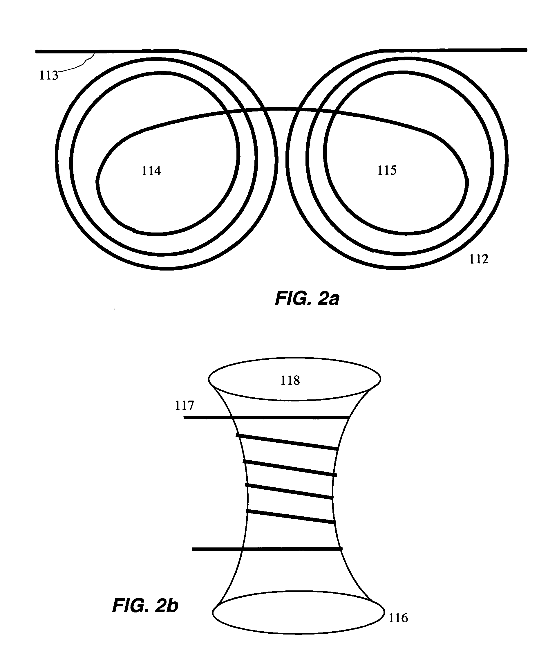
[0061] An alternative embodiment 116 of coiling fibers with smoothly varying radius of curvature is shown in FIG. 2b, where fiber 117 is coiled onto a bi-conical form. The two embodiments shown in FIGS. 2a and 2b are to serve only as examples and a large number of additional geometries can be easily conceived. The two important parameters are 1) a smoothly varying radius of curvature throughout the fiber as well as 2) a smoothly varying radius of curvature throughout the whole fiber length where the fiber experiences any bend loss.
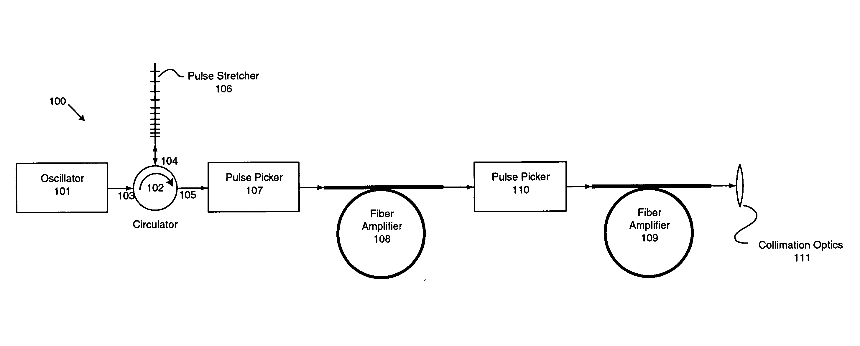
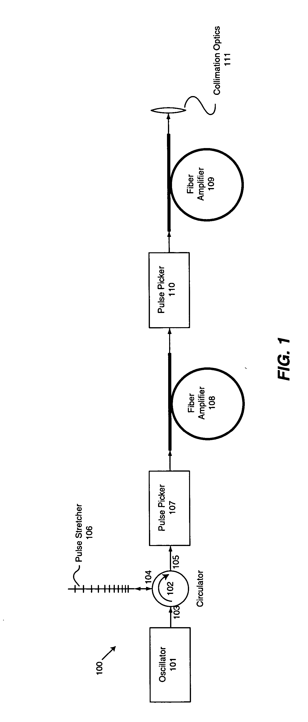
[0062] Referring back to FIG. 1, for positively chirped seed pulses, self-phase modulation in the amplification process leads to spectral broadening and the generation of output pulses with increased pulse chirp. By selecting a negatively chirped fiber pulse stretcher grating 106, self-phase modulation produces spectral narrowing, resulting in the generation of pulses with a spectral output width smaller than the injected spectral width and a reduction in ...
embodiment 200
[0064]FIG. 3 displays an even more compact embodiment 200 for the generation and amplification of unidirectionally chirped pulses. A monolithic fast tunable diode laser 201 is used for generating broad bandwidth unidirectionally chirped optical pulses, which are amplified in fiber amplifier 202 or an equivalent fiber amplifier chain. The fast tunable diode laser 201 is preferably implemented as a three section, distributed Bragg reflector (DBR) diode laser as described in U.S. Pat. No. 5,400,350 issued to Galvanauskas. The DBR diode laser comprises an active gain section, a phase control section and a Bragg reflector section. An application of current pulses to the phase control and Bragg reflector section of this laser at each laser pulse leads to a wavelength shift during the laser emission. By appropriate control of the magnitude and the timing for this tuning, a negatively or positively chirped pulse with pulse durations as short as 100 picoseconds can be generated. Spectral ban...
embodiment 100
[0073] The embodiment displayed in FIG. 5 has the advantage that the gain bandwidth of the solid-state amplifier can be matched to the fiber amplifier system. For example, 1 nanosecond pulses with a spectral bandwidth of 0.6 nanometers and a pulse energy exceeding 100 microjoules, centered at a wavelength of 1064 nanometers can be generated in a fiber amplifier chain in conjunction with a diode seed laser, for injection into a Nd:YVO4 amplifier, which has a spectral bandwidth of approximately 0.9 nanometers. As another example, a mode locked Yb-fiber oscillator with center wavelength of 1064 nanometers and a bandwidth of several nanometers can be amplified and spectrally narrowed as described in embodiment 100 and matched to the gain bandwidth of the Nd:YVO4 solid-state amplifier. Thus, 100 picosecond pulses with an energy of around 100 microjoules and higher can be generated in a fiber amplifier chain and efficiently amplified in a subsequent solid-state amplifier. Without exploita...
PUM
| Property | Measurement | Unit |
|---|---|---|
| Length | aaaaa | aaaaa |
| Time | aaaaa | aaaaa |
| Time | aaaaa | aaaaa |
Abstract
Description
Claims
Application Information