Braided spar for a rotor blade and method of manufacture thereof
- Summary
- Abstract
- Description
- Claims
- Application Information
AI Technical Summary
Benefits of technology
Problems solved by technology
Method used
Image
Examples
Embodiment Construction
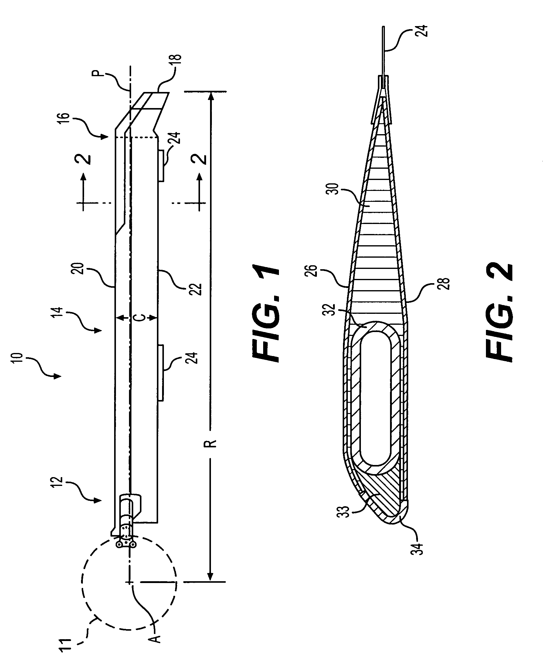
[0022]FIG. 1 schematically illustrates an exemplary main rotor blade assembly 10 mounted to a rotor hub assembly 11 (illustrated schematically) for rotation about an axis of rotation A. The main rotor blade 10 includes an inboard section 12, an intermediate section 14, and an outboard section 16. The inboard, intermediate, and outboard sections 12, 14, 16 define the span of the main rotor blade 10. The blade sections 12, 14, 16 define a blade radius R between the axis of rotation A and a blade tip 18.
[0023] A plurality of main rotor blade assemblies 10 project substantially radially outward from the hub assembly 11 and are supported therefrom in one of numerous attachments. Any number of blades 10 may be used with the rotor system 10. It should be understood that although a rotor system is illustrated in the disclosed embodiment, other applications which will benefit from a hollow composite member such as flex beams, main rotors, tail rotors, propellers, wing spars, turbines, windm...
PUM
| Property | Measurement | Unit |
|---|---|---|
| Angle | aaaaa | aaaaa |
| Angle | aaaaa | aaaaa |
| Angle | aaaaa | aaaaa |
Abstract
Description
Claims
Application Information
 - R&D
- Intellectual Property
- Life Sciences
- Materials
- Tech Scout
- Unparalleled Data Quality
- Higher Quality Content
- 60% Fewer Hallucinations
Browse by: Latest US Patents, China's latest patents, Technical Efficacy Thesaurus, Application Domain, Technology Topic, Popular Technical Reports.
© 2025 PatSnap. All rights reserved.Legal|Privacy policy|Modern Slavery Act Transparency Statement|Sitemap|About US| Contact US: help@patsnap.com


