Lateral flow diagnostic devices with instrument controlled fluidics

a fluidic control and diagnostic device technology, applied in the direction of electrolysis, diaphragm, isotope separation, etc., can solve the problems of inability to achieve quantitative analysis, limited quantitative and sensitive detection using such devices, and prior art devices that are not generally suitable for quantitative assays, etc., to achieve enhanced sensitivity detection, advanced fluidic capability, and convenient use

Active Publication Date: 2005-03-03
SIEMENS HEALTHCARE DIAGNOSTICS INC
View PDF73 Cites 33 Cited by
  • Summary
  • Abstract
  • Description
  • Claims
  • Application Information

AI Technical Summary

Benefits of technology

, one-step prior art lateral flow diagnostic devices lack the amplification, washing and high sensitivity detection steps needed for quantitative determination of analyte levels. Micro-channel devices in the prior art have not incorporated chemical entities in the channels and reagents storage within the device. The prior art does not teach a one-step assay device that is as easy to use and inexpensive to manufacture but which features the more advanced fluidic capability found in high sensitivity quantitative laboratory-based assay technologies and in which assay performance is largely independent of the fluidic components and reaction vessels in which the assay is performed. This invention addresses the need to adapt standard lateral flow elements to incorporate more advanced fluidic elements for use in conjugate label application, washing, amplification and enhanced sensitivity detection without sacrificing the speed, simplicity of use and low cost of standard lateral flow technologies.

Problems solved by technology

Generally, quantitative and sensitive detection using such devices is limited.
However, devices of the prior art are not generally suitable for use in quantitative assays for two reasons.
Firstly, they are usually formatted with visually observable reporters, which are suitable for threshold yes / no detection, but unsuitable for quantitative analysis.
Secondly, both the concentration of the complex formed between the analyte and the reporter conjugate and the amount of binding at the capture site are flow rate dependent.
The variability of device operation, particularly sample flow rate and sample evaporation, creates significant variability in the detected signal.
However, even quantitative prior-art lateral flow devices, have not matched the sensitivity of more complex laboratory based assays.
The first reason is the absence of rigorous wash steps, which may be required to fully remove unbound reporter conjugate from the capture region.
Because they are less sensitive, lateral flow devices are only used in routine analysis of higher abundance analytes.
These kit-based devices typically require multiple reagent additions and wash steps and consequently are not well adapted to point-of care applications where a simple one-step procedure is preferable.
However, generally in these prior art devices, reagents are stored off-chip and need to be introduced during use.
Also, devices of these technologies have generally operated in a continuous flow format because valves have been difficult to construct.
In summary, one-step prior art lateral flow diagnostic devices lack the amplification, washing and high sensitivity detection steps needed for quantitative determination of analyte levels.
Micro-channel devices in the prior art have not incorporated chemical entities in the channels and reagents storage within the device.
The prior art does not teach a one-step assay device that is as easy to use and inexpensive to manufacture but which features the more advanced fluidic capability found in high sensitivity quantitative laboratory-based assay technologies and in which assay performance is largely independent of the fluidic components and reaction vessels in which the assay is performed.

Method used


Image

  • Lateral flow diagnostic devices with instrument controlled fluidics
  • Lateral flow diagnostic devices with instrument controlled fluidics
  • Lateral flow diagnostic devices with instrument controlled fluidics

Examples


experiment 1

to a Vented Channel

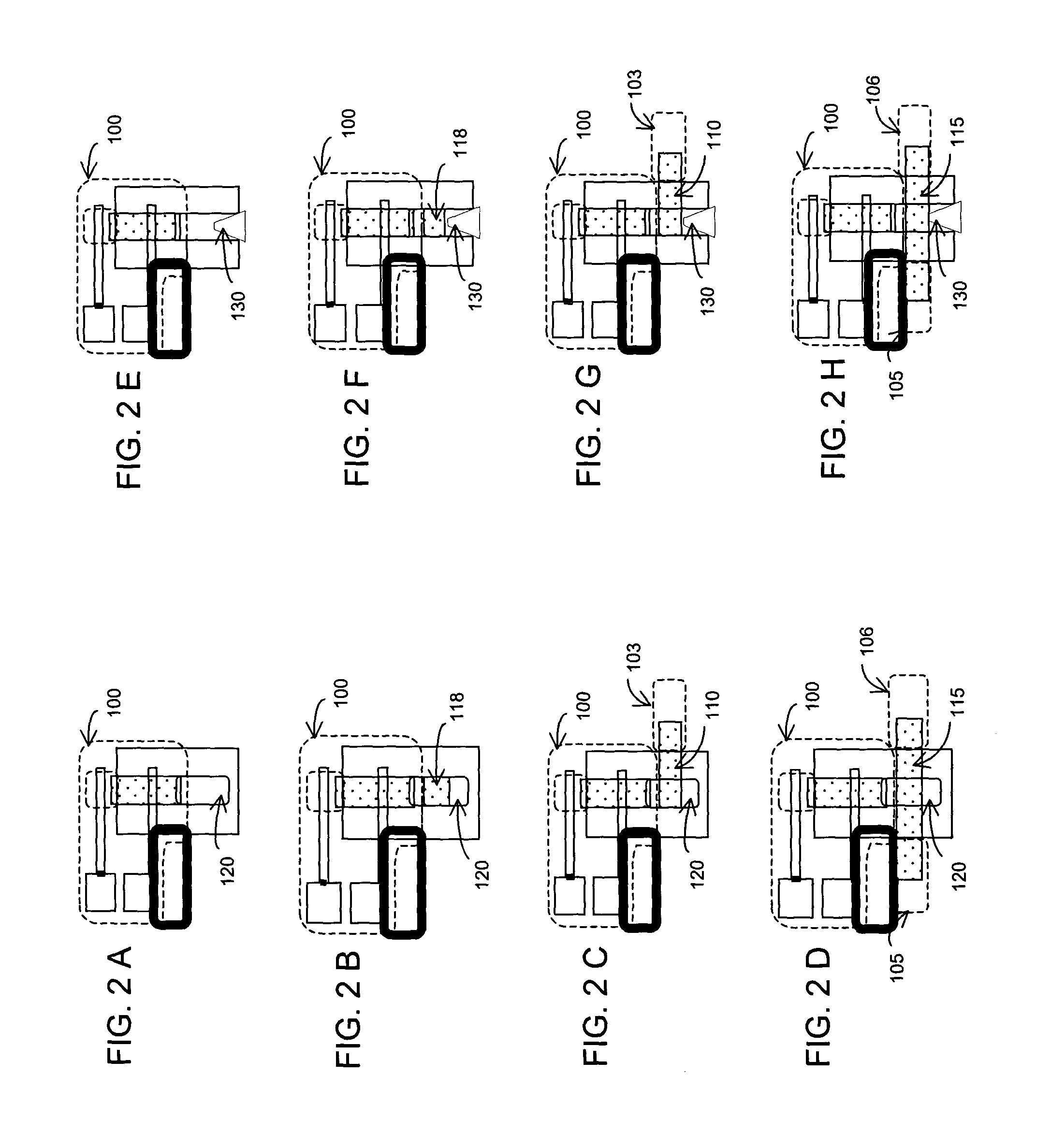
To investigate the injector's pumping characteristics with no fluidic load injectors with a vented air channel at their effluent end but with no other fluid-receiving elements were constructed. This configuration is depicted in the schematic FIG. 2E. The injector was first primed by applying an aqueous fluid to the fluid application end of the initially dry injector. Next, a voltage was applied between the integral electrodes and the volume flow rate was measured by measuring the length of fluid in the vent channel of known cross-sectional area at different times. From this the electro-osmotic mobility (EOM) was obtained.

Best performance was obtained with injector fluids comprising aqueous solutions of low conductivity: an electrolyte concentration of about 2 mM was preferred and 10 mM was the upper useful range. A micro-porous cellulose nitrate / acetate (Millipore MF membrane GSWP) having a porosity of 0.75 with 0.11 micrometer pore radius was used as the injec...

experiment 2

to an Enclosed Chamber

Injectors with an enclosed air chamber at their effluent end but with no other fluid-receiving elements were constructed to investigate the injector's pumping characteristics with infinite fluidic load. This configuration is depicted in the schematic FIG. 2A. First, the injector was primed by applying an aqueous fluid to the fluid application end of the initially dry injector. Next, a voltage was applied between the integral electrodes. Fluid was displaced from the injector's effluent end into the enclosed channel of initial volume V1 and at P1=1 atmosphere. The air was compressed as the fluid filled the chamber until steady state when the fluid flow stopped. The new volume of air was V2<V1. The resulting pressure that stopped flow was calculated from Boyle's law to give P2=V1 / V2. A micro-porous cellulose nitrate / acetate with 0.11 micrometer pore radius was used.

Pore Radius of Injector's Micro-Porous Flow Path:

Trapezoidal injectors (input end width 4 ...

experiment 3

to a Fluid-Receiving Element at an Enclosed Air Chamber

To investigate the pumping characteristics of an injector connected to a fluid-receiving element with a flow resistance injectors with an enclosed air chamber at their effluent end connected to a fluid-receiving strip element at a fluid-receiving location along its length were constructed. Both rectangular and trapezoidal injectors were investigated. The configuration of injector and fluid-receiving element is as depicted in the schematic FIG. 2D. The various steps in the operation of the injector of this configuration are depicted in FIG. 3A-3E. A first fluid was applied to the fluid application end of the initially dry strip (FIG. 3A). The strip was filled with the first fluid by lateral capillary flow (FIG. 3B). Next, the initially dry injector was primed by applying an aqueous fluid (2 mM DEA solution) to its fluid application end (FIG. 3C). The injector filled to its effluent end by capillary flow (FIG. 3D). A voltage was ...


PUM

PropertyMeasurementUnit
radiusaaaaaaaaaa
radiusaaaaaaaaaa
electric potentialaaaaaaaaaa

Abstract

Devices with lateral flow elements and integral fluidics are disclosed. The integral fluidics consist of injector pumps comprised of fluidic elements under instrument control. The fluidic element of an injector pump is fluidically connected to lateral flow elements and can be used to control fluid entry into containment chambers referred to as micro-reactors. The lateral flow elements comprise conductor elements that can be used for sample application and transport of analyte contained in the sample to the micro-reactor. Fluidic transport through the fluidic element of the injector pump is under instrument-control. Both the lateral flow element and the fluidic element may contain chemical entities incorporated along their length. The chemical reactions that can be used for analyte detection using the devices are described. Also described are methods of manufacture of these devices.

Description

FIELD OF THE INVENTION The present invention relates generally to analytical devices and micro-arrays containing integral fluidic input / output devices for sample application and washing steps. More particularly, the present invention relates to the input / output fluidic devices constructed from planar solid-phase hydrophilic matrix circuits containing dry chemical reagents for use in point of care diagnostics and other micro-scale analyses. BACKGROUND OF THE INVENTION Lateral flow diagnostic devices including a micro-porous element along which a sample fluid flows laterally and a capture region for binding an analyte of interest contained in the sample fluid are known in the art. A lateral flow diagnostic device of simple construction includes a rectangular micro-porous strip, which supports capillary fluid flow along its length. Generally, quantitative and sensitive detection using such devices is limited. More recently, devices that incorporate instrumentation that allow for quan...

Claims


Application Information

Patent Timeline
Patent Type & Authority Applications(United States)
IPC IPC(8): B01L3/00F04B19/00G01N1/28
CPCB01L3/50273B01L2200/0673B01L2200/10Y10T436/2575B01L2400/0406B01L2400/0418F04B19/006B01L2300/0816
Inventor LAUKS, IMANTSPIERCE, RAYMOND J.WOJTYK, JAMESBERGEVIN, BENOIT R.
Owner SIEMENS HEALTHCARE DIAGNOSTICS INC
Why Eureka
Try Eureka