Sputtering using an unbalanced magnetron

a magnetron and unbalanced technology, applied in the field of materials sputtering, can solve the problems of high heat generation, poor quality of deposited films, and relatively new hdp pvd reactors, and achieve the effects of high target power, high density, and increased plasma density

Inactive Publication Date: 2005-03-10
FU JIANMING +3
View PDF54 Cites 19 Cited by
  • Summary
  • Abstract
  • Description
  • Claims
  • Application Information

AI Technical Summary

Benefits of technology

The invention also includes sputtering under conditions, such as a sufficiently high target power and high magnetic field away from ...

Problems solved by technology

Many of the problems are associated with contact and via holes.
Such high aspect ratios present a problem for sputtering because most forms of sputtering are not strongly anisotropic, a cosine dependence off the vertical being typical, so that the initially sputtered material preferentially deposits at the top of the hole and may bridge it, thus preventing the filling of the bottom of the hole and creating a void in the via metal.
However, HDP PVD reactors are new and relatively expensive, and the quality of the deposited films is not always the best.
This type of reactor, though, runs very hot and the complexly shaped targets are very expensive.
The variable thickness is particularly serious when the sputtered copper layer is being used as a seed layer of a predetermined minimum thickness for a subsequent deposition process such as electroplating to complete the copper hole filling.
A further problem in the prior art is that the sidewall coverage tends to be asymmetric with the side facing the center of the target being more heavily coated than the more shielded...

Method used


Image

  • Sputtering using an unbalanced magnetron
  • Sputtering using an unbalanced magnetron
  • Sputtering using an unbalanced magnetron

Examples


Embodiment Construction

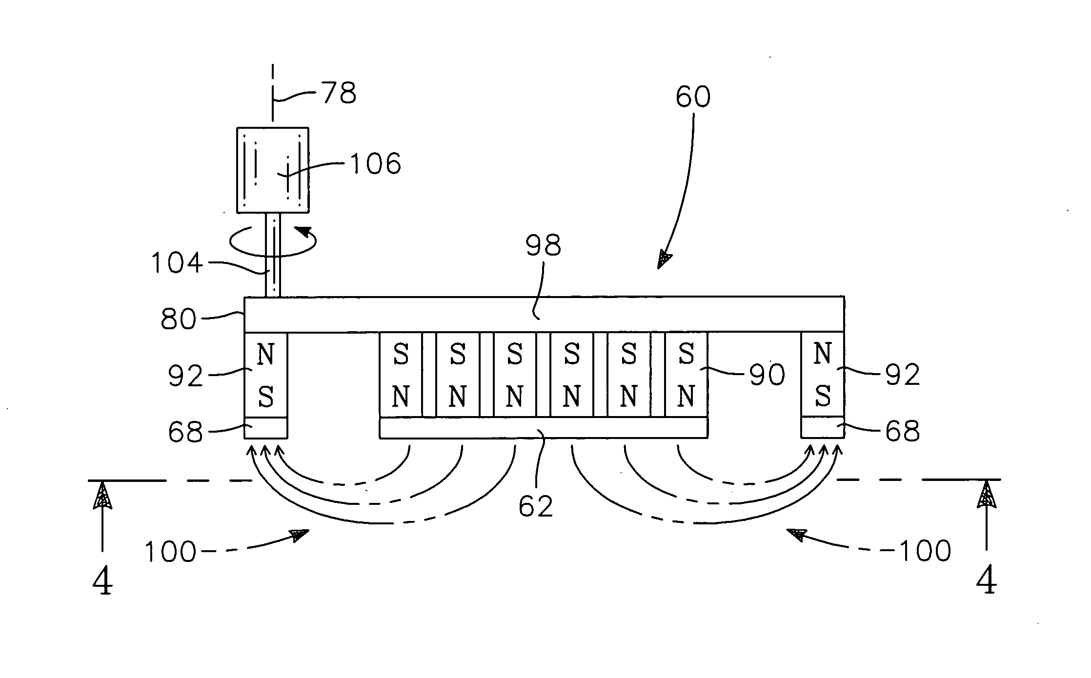
One embodiment of the invention is a racetrack magnetron 60, illustrated in plan view in FIG. 4. The racetrack magnetron 60 has a central bar-shaped pole face 62 of one magnetic polarity having opposed parallel middle straight sides 64 connected by two rounded ends 66. The central, bar-shaped pole face 62 is surrounded by an outer elongated ring-shaped pole face 68 of the other polarity with a gap 70 of nearly constant width separating the bar-shaped and ring-shaped pole faces 62, 68. The outer pole face 68 of the other magnetic polarity includes opposed parallel middle straight sections 72 connected by two rounded ends 74 in general central symmetry with the inner pole face 62. The middle sections 72 and rounded ends 74 are bands having nearly equal widths. Magnets, to be described shortly, cause the pole faces 62, 68 to have opposed magnetic polarities. A backing plate, also to be described shortly, provides both a magnetic yoke between the magnetically opposed pole faces 62, 68 ...


PUM

PropertyMeasurementUnit
Pressureaaaaaaaaaa
Ratioaaaaaaaaaa
Areaaaaaaaaaaa

Abstract

A sputtering process and magnetron especially advantageous for low-pressure plasma sputtering or sustained self-sputtering, in which the magnetron has a reduced area but full target coverage. The magnetron includes an outer pole face surrounding an inner pole face with a gap therebetween. The outer pole of the magnetron of the invention is smaller than that of a circular magnetron similarly extending from the center to the periphery of the target and has a substantially larger total magnetic intensity. Thereby, sputtering at low pressure and high ionization fraction is enabled.

Description

FIELD OF THE INVENTION The invention relates generally to sputtering of materials. In particular, the invention relates to the magnetron creating a magnetic field to enhance sputtering and the resultant sputtering methods. BACKGROUND ART Sputtering, alternatively called physical vapor deposition (PVD), is the most prevalent method of depositing layers of metals and related materials in the fabrication of semiconductor integrated circuits. A conventional PVD reactor 10 is illustrated schematically in cross section in FIG. 1, and the illustration is based upon the Endura PVD Reactor available from Applied Materials, Inc. of Santa Clara, Calif. The reactor 10 includes a vacuum chamber 12 sealed to a PVD target 14 composed of the material, usually a metal, to be sputter deposited on a wafer 16 held on a heater pedestal 18. A shield 20 held within the chamber protects the chamber wall 12 from the sputtered material and provides the anode grounding plane. A selectable DC power supply 22...

Claims


Application Information

Patent Timeline
IPC IPC(8): H01J37/34C23C14/35
CPCH01J37/3455H01J37/3408C23C14/35
Inventor FU, JIANMINGGOPALRAJA, PRABURAMCHEN, FUSENFORSTER, JOHN
Owner FU JIANMING
Why Eureka
Try Eureka