Integrateable band filter using waveguide grating routers

a waveguide grating router and integrated technology, applied in the field of optical band filters, can solve the problems of increasing the size and complexity of filters, increasing the cost of mass production on any scale, and exhibiting significant chromatic dispersion of filters, so as to reduce ripple, reduce the effect of loss band, and easy fabrication

Active Publication Date: 2005-03-10
WSOU INVESTMENTS LLC +1
View PDF7 Cites 10 Cited by
  • Summary
  • Abstract
  • Description
  • Claims
  • Application Information

AI Technical Summary

Benefits of technology

The present invention advantageously provides a compact, easy to fabricate, reduced ripple (i.e., substantially flat passband), low loss band filter that is capable of being constructed in planar lightwave circuit (PLC) technology.

Problems solved by technology

Thin-film interference filters also exhibit significant chromatic dispersion; they require more than ten cavities to achieve sharp passband corners which increases the filter size and complexity appreciably; and they typically require a cascade of elements to demultiplex more than two bands.
As these filters are assembled into the final band filter package, they require extensive characterization and matching, tedious hand assembly, and expensive hermetic packages making mass production on any scale expensive.
Bulk grating band filters also exhibit large form factors and, like thin-film filters, require tedious hand assembly and expensive hermetic packages.
In addition, these filters exhibit more loss than their thin-film counterparts.
However, previously proposed band filters based on PLC technology utilized cascaded Mach-Zender Interferometers (MZI), which are exceedingly large in form factor, are limited to de / multiplex only a few flat bands, and usually lack sharply defined passband corners.
For CWDM applications in particular, the limitation on the number of bands arises because these filters are designed with a constant frequency difference between de / multiplexer channels rather than a constant wavelength difference as dictated by the CWDM scheme.

Method used


Image

  • Integrateable band filter using waveguide grating routers
  • Integrateable band filter using waveguide grating routers
  • Integrateable band filter using waveguide grating routers

Examples


Embodiment Construction

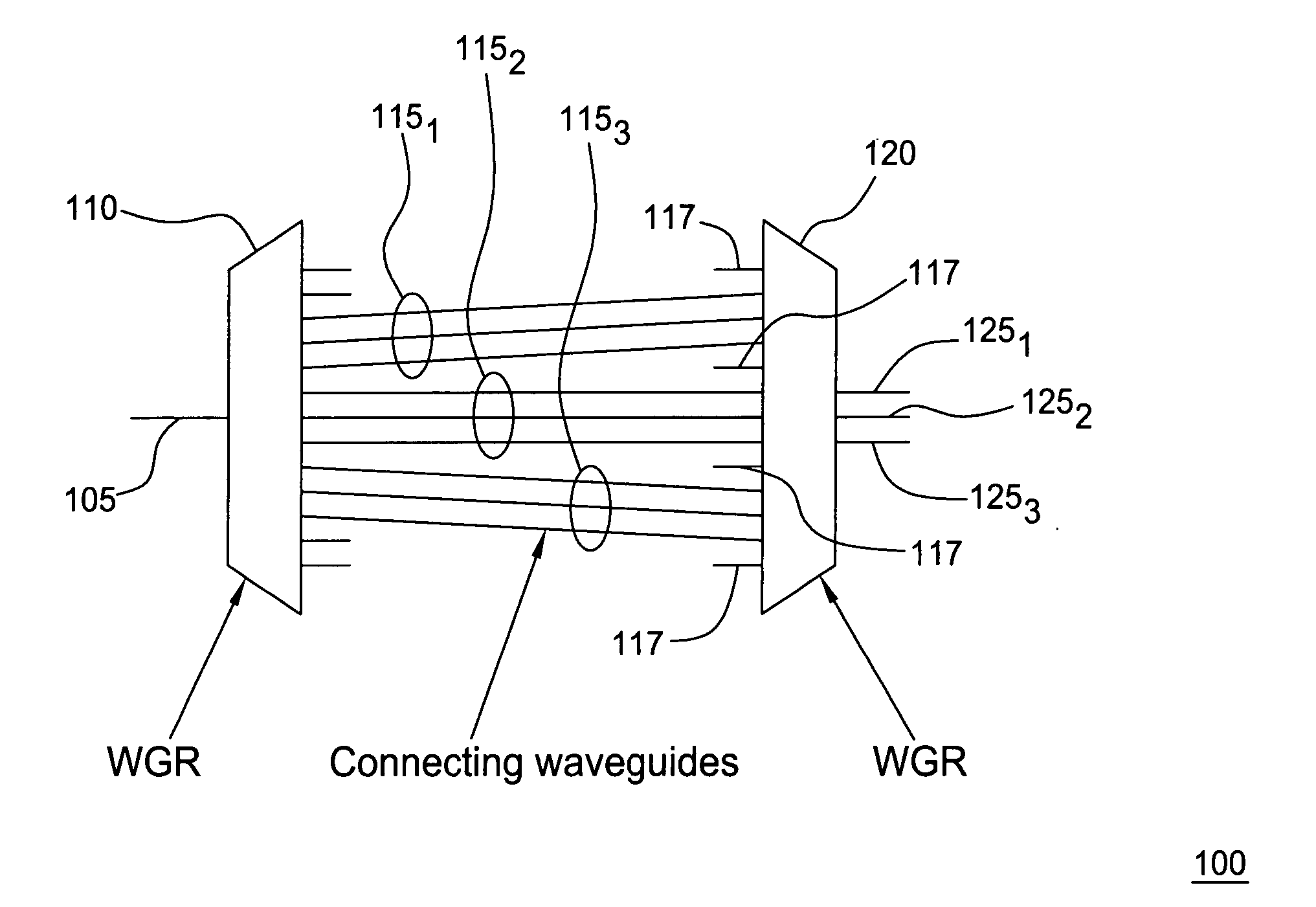
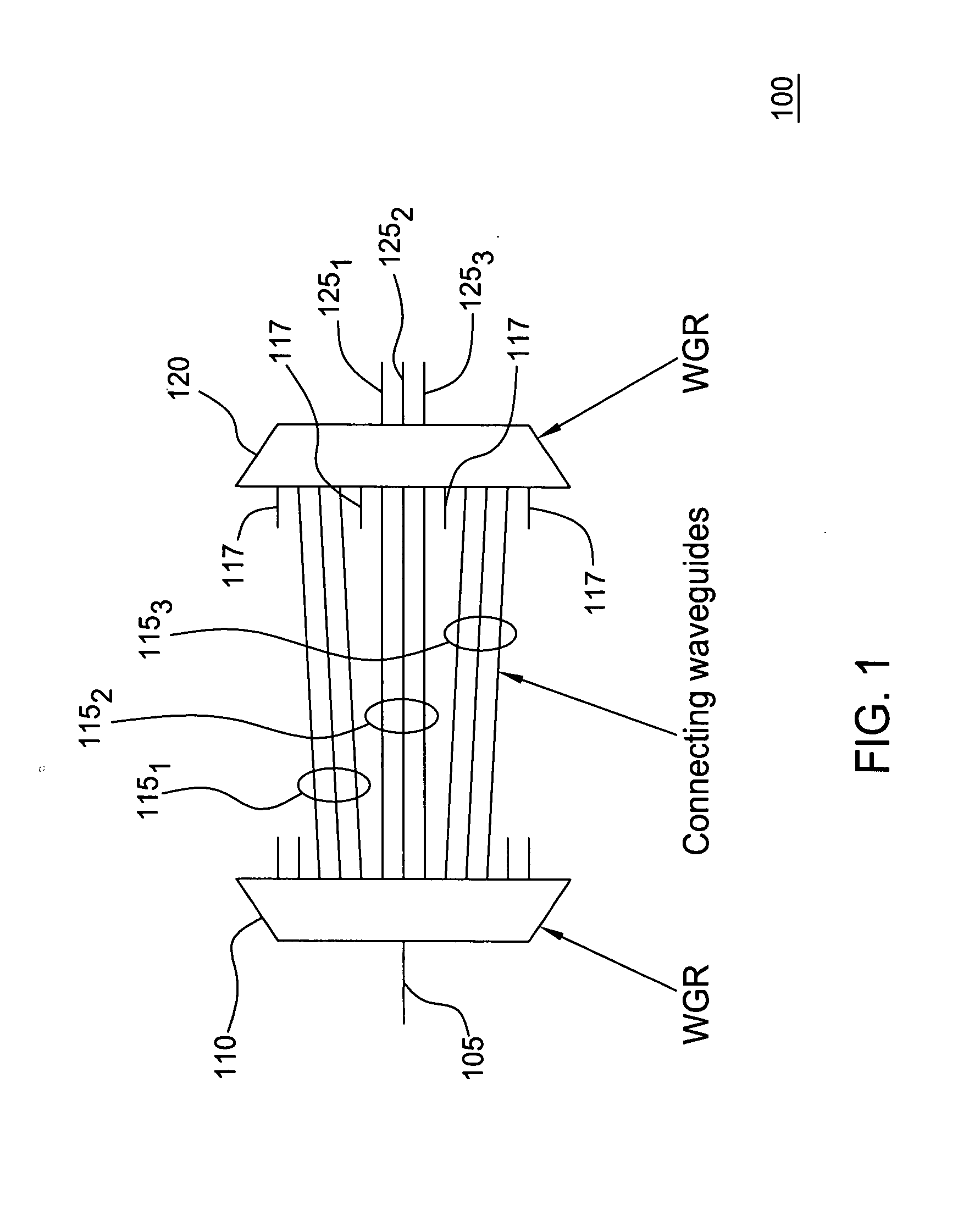
Optical filters based on waveguide grating router structures have been described in the art. In particular, one such filter wherein two waveguide grating routers are coupled together by a region including two additional waveguide gratings separated by a plurality of optical elements such as phase shifters, switches and the like is described in U.S. Pat. No. 6,603,898 entitled “Apparatus and method for achieving a smooth spectral response optical filter”, issued Aug. 5, 2003, which is incorporated herein by reference in its entirety.

Although various embodiments of the present invention herein are being described with respect to a 1×3 optical band filter, it will be appreciated by those skilled in the art informed by the teachings of the present invention that the concepts of the present invention are applicable to band filters comprising substantially any number or combination of inputs and outputs.

FIG. 1 depicts a high-level block diagram of one embodiment of a band filter in ac...


PUM


Abstract

The inventors propose herein a novel band filter design for planar lightwave circuits. In one embodiment of the present invention, the band filter includes two waveguide grating routers interconnected by a third waveguide grating, wherein waveguides comprising the third waveguide grating have unequal path lengths. In addition, the waveguides in the third grating are partitioned into sets of adjacent waveguides wherein each set corresponds to a particular wavelength band for the filter. The individual sets of waveguides are spaced at their connection to the second waveguide grating router such that optical signals within predetermined, different optical wavelength bands are routed to different output ports of the band filter. Some of the advantages of this novel band filter include compactness, sharp passband corners, low spectral ripple, and a lack of chromatic dispersion.

Description

FIELD OF THE INVENTION This invention relates to the field of optical band filters and, more specifically, to integrated optical band filters having reduced ripple. BACKGROUND OF THE INVENTION A band filter is a device that is able to separate an incoming optical spectrum into bands (i.e., when used as a demultiplexer) or combine separate optical bands into an output optical spectrum (i.e., when used as a multiplexer), ideally with sharp passband corners. Each band includes one or more optical channels from a multiplexed signal having a plurality of separate optical channels. Band filters are useful in both dense (D) and coarse (C) wavelength-division multiplexed (WDM) systems. In DWDM systems, band filters are typically used for de / multiplexing with a high spectral efficiency or for permitting the use of narrowband optical amplifiers, dispersion compensators, add-drop filters, etc. In CWDM systems, band filters are typically used for de / multiplexing without transmitter temperatur...

Claims


Application Information

Patent Timeline
Patent Type & Authority Applications(United States)
IPC IPC(8): G02B6/34
CPCG02B6/12021
Inventor DOERR, CHRISTOPHER RICHARD
Owner WSOU INVESTMENTS LLC
Why Eureka
Try Eureka