Process for strengthen grain boundaries of an article made from a Ni based superalloy

a superalloy and grain boundary technology, applied in the direction of crystal growth process, solid state diffusion coating, after-treatment details, etc., can solve the problems of inability to maintain the desired life of the component or the desired, and in the practice of casting a large perfect single crystal component, etc., to achieve the effect of partially restoring the mechanical properties of the defect area

Active Publication Date: 2005-03-24
ANSALDO ENERGIA SWITZERLAND AG
View PDF8 Cites 3 Cited by
  • Summary
  • Abstract
  • Description
  • Claims
  • Application Information

AI Technical Summary

Benefits of technology

[0018] With the present invention the mechanical properties of the defect area are partially restored. The presence of the grain boundary strengthening elements eliminated the detrimental effect of aforementioned casting defects. The present invention relates to the repair of casting defects such as recrystallized grains, spurious grains, slivers and freckles of a single crystal (SX) or directionally solidified (DS) article such as a blade or vane or any other gas turbine component.

Problems solved by technology

Casting a large perfect single crystal component is in practice extremely difficult, with most such components being subject to defects such as grain boundaries, freckles, equiaxed stray grains and microporosity among others.
These defects generally weaken the components at high temperature, resulting in an inability to maintain a desired life of the component or a desired temperature of operation of the turbine, which will ensure high turbine efficiency, without risking component failure initiated at the defect.
However, to demand nothing but perfect single crystal articles from a foundry would incur a very high scrap rate and concomitant high per-part costs.
One of the most prevalent defects are grain boundaries, which are particularly harmful to the single crystal components high temperature properties.
In addition the presence of these elements in solution in the grains and along the grain boundaries slows down diffusion processes at high temperatures, which is a major source of grain boundary weakness.
Several complicated process steps are necessary which may cause further component damage due to heat input.
Additionally, the replaced material exhibits usually a degradation of all properties compared to the parent material.

Method used


Image

  • Process for strengthen grain boundaries of an article made from a Ni based superalloy
  • Process for strengthen grain boundaries of an article made from a Ni based superalloy
  • Process for strengthen grain boundaries of an article made from a Ni based superalloy

Examples


Embodiment Construction

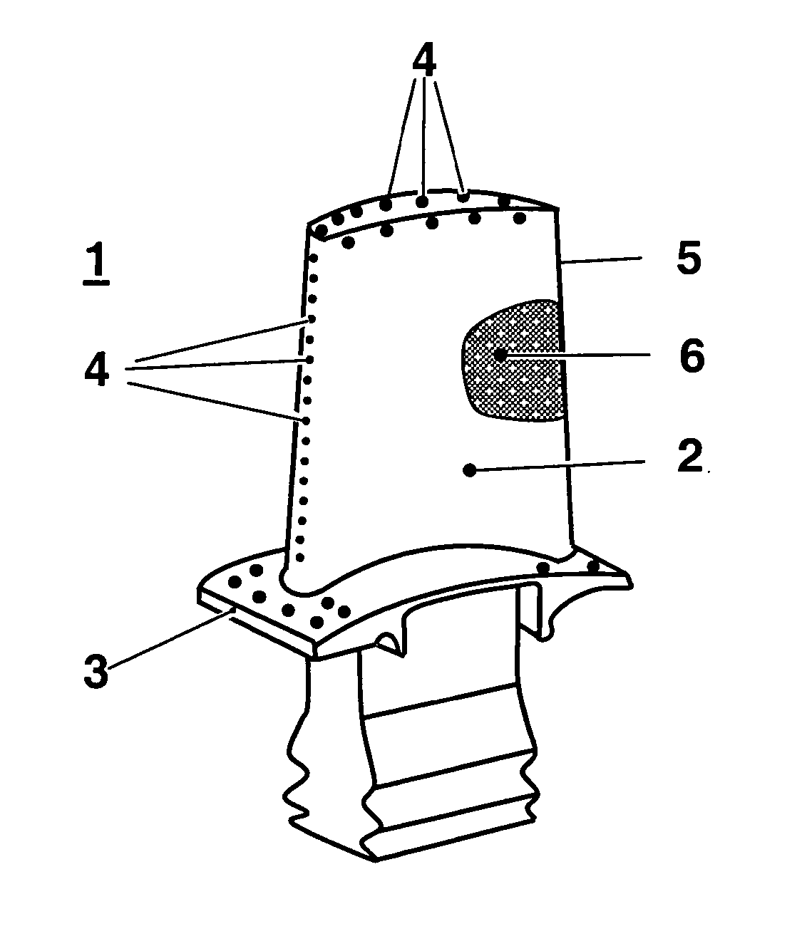
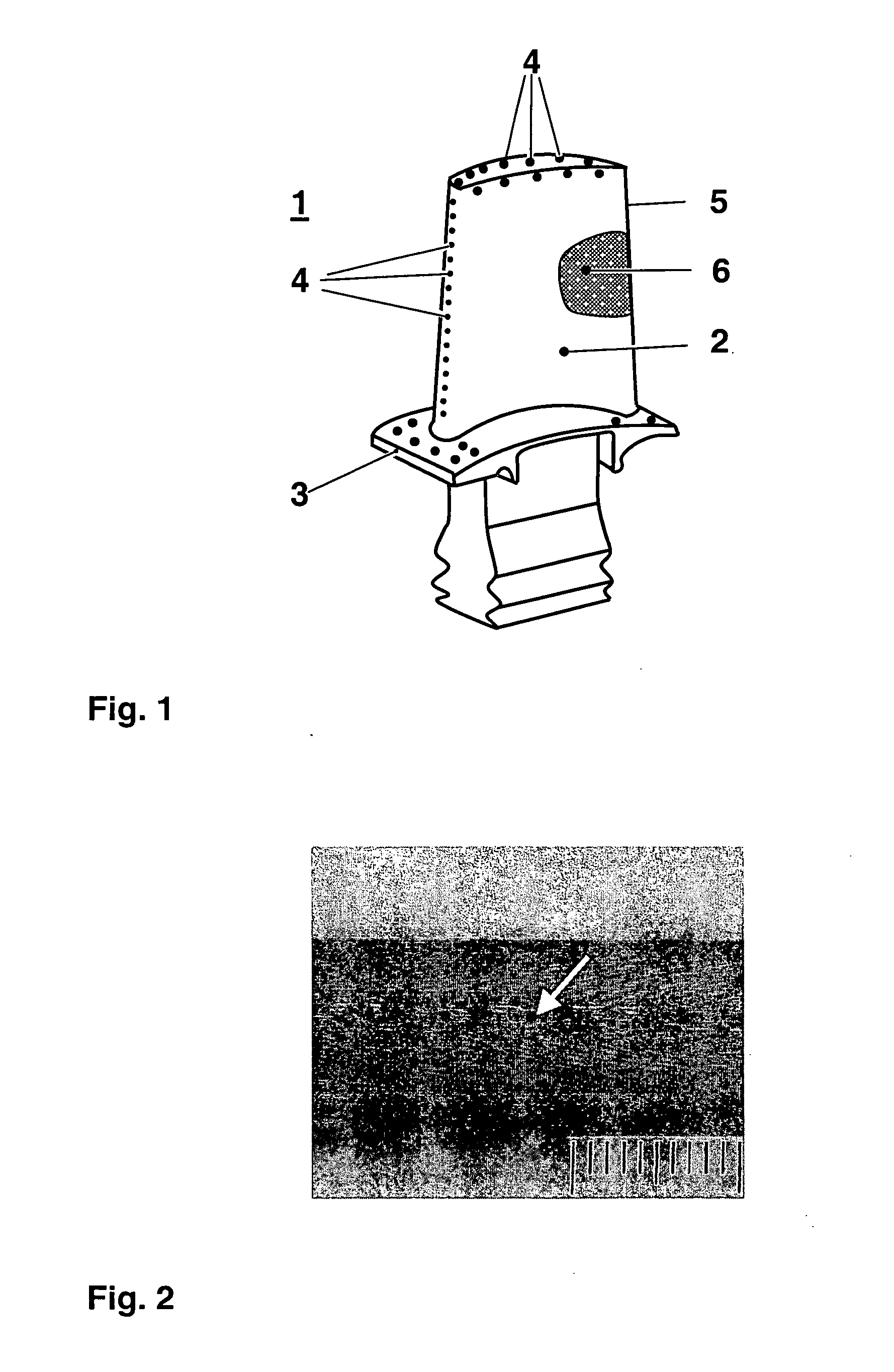
[0027] The present invention is generally applicable to components that operate within environments characterised by relatively high temperature, and are therefore subjected to severe thermal stresses and thermal cycling. Notable examples of such components include the high and low pressure nozzles and blades, shrouds, combustor liners and augmentor hardware of gas turbine engines. FIG. 1 shows as an example such an article 1 as blades or vanes comprising a blade 2 against which hot combustion gases are directed during operation of the gas turbine engine, a cavity, not visible in FIG. 1, and cooling holes 4, which are on the external surface 5 of the component 1 as well as on the platform 3 of the component. Through the cooling holes 4 cooling air is ducted during operation of the engine to cool the external surface 5. The external surface 5 is subjected to severe attack by oxidation, corrosion and erosion due to the hot combustion gases. In many cases the article 1 consists of a ni...


PUM


Abstract

It is disclosed a method for strengthen the grain boundaries of an article (1) made from a Ni based superalloy while the article (1) is in the solid state and containing at least one grain boundary. A surface diffusion process is applied to the article (1) to enrich the at least one grain boundary with grain boundary strengthening elements of one or a combination of boron, hafnium, zirconium without forming brittle precipitates like borides or carbides.

Description

FIELD OF THE INVENTION [0001] This invention relates according to claim 1 to a method for strengthen grain boundaries of a single crystal (SX) or directionally solidified (DS) article made from a Ni based superalloy while the article is in the solid state after casting. STATE OF THE ART [0002] Single crystal turbine components are manufactured from Ni based superalloys using a directional solidification technique. Casting a large perfect single crystal component is in practice extremely difficult, with most such components being subject to defects such as grain boundaries, freckles, equiaxed stray grains and microporosity among others. These defects generally weaken the components at high temperature, resulting in an inability to maintain a desired life of the component or a desired temperature of operation of the turbine, which will ensure high turbine efficiency, without risking component failure initiated at the defect. However, to demand nothing but perfect single crystal articl...

Claims


Application Information

Patent Timeline
Patent Type & Authority Applications(United States)
IPC IPC(8): C22C1/00C23C10/28C23C10/30C23C10/34C23C10/52C23C10/58C23C10/60C30B29/52C30B33/00
CPCC22C1/00C23C10/28C23C10/34C30B33/00C23C10/58C23C10/60C30B29/52C23C10/52
Inventor MULLER, STEFFENROESLER, JOACHIM
Owner ANSALDO ENERGIA SWITZERLAND AG
Why Eureka
Try Eureka