Apparatus and methods relating to concentration and shaping of illumination

a technology of illumination and apparatus, applied in the field of apparatus and methods relating to concentration and shaping of illumination, can solve the problems that the type of optical arrangement is not suitable for high intensity illumination using bright point sources, and achieve the effect of enhancing the performance of a total internal reflectance prism and enhancing the performance of a first surface reflector reflective piecewise rotational

Inactive Publication Date: 2005-03-24
MACKINNON NICHOLAS B +2
View PDF2 Cites 19 Cited by
  • Summary
  • Abstract
  • Description
  • Claims
  • Application Information

AI Technical Summary

Benefits of technology

In other aspects, the present invention includes methods for enhancing the performance of a first surface reflector reflective piecewise rotational array when the beam is to be folded by an angle θ comprising determing suitable angles of the reflecting planes of the array by calculating the microarray angle a according to the equation: α=12⁢(tan-1⁡(2tan⁡(θ)))
In other aspects, the present invention includes methods for enhancing the performance of a total internal reflectance prism type reflective piecewise rotational array when the beam is to be folded by an angle θ comprising determing suitable angles of the reflecting planes of the array by calculating the microarray angle α according to the equation, α=12⁢(tan-1⁡(2tan⁡(θ)))

Problems solved by technology

While traditional porro prisms arrayed and set to deflect a beam at 45 degrees can be useful for concentrating general diffuse illumination for a spectrometer, this type of optical arrangement is not as appropriate for high intensity illumination using bright point sources.

Method used


Image

  • Apparatus and methods relating to concentration and shaping of illumination
  • Apparatus and methods relating to concentration and shaping of illumination
  • Apparatus and methods relating to concentration and shaping of illumination

Examples


Embodiment Construction

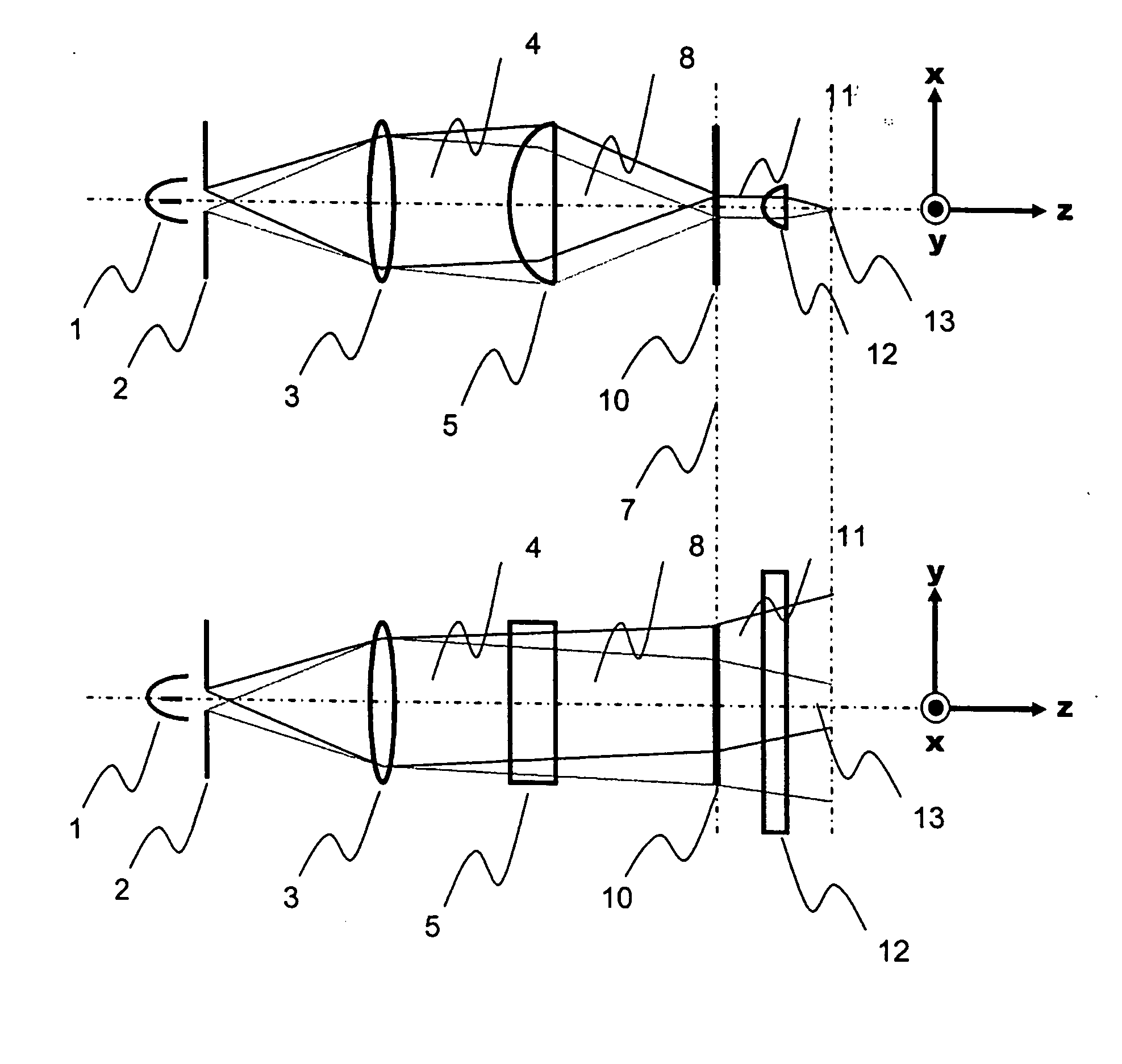
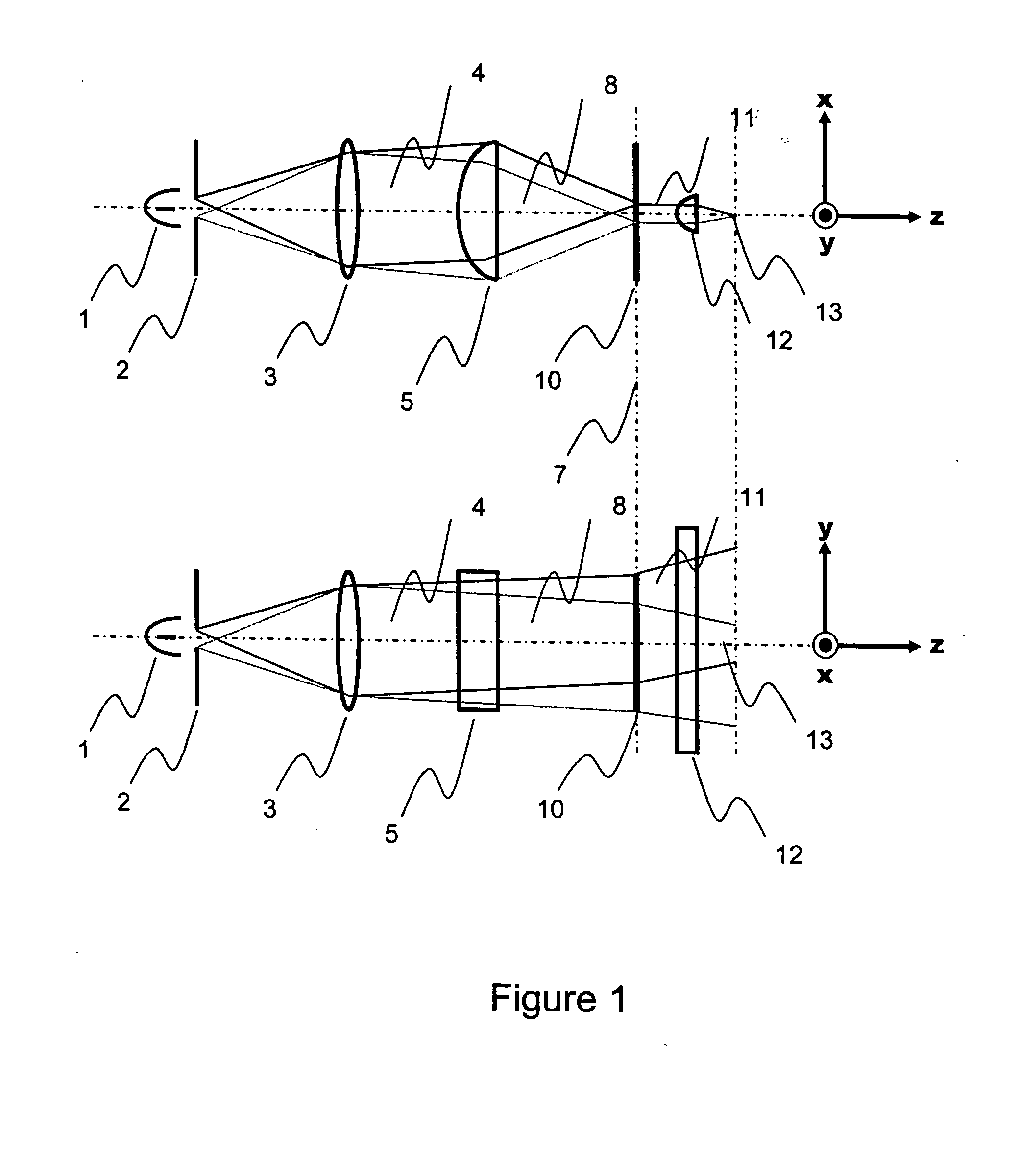
The present invention comprises components for conditioning light emitted by a desired light source such as an arc lamp, filament lamp, light emitting diode (LED) or an optical fiber, to direct that illumination such that it may be precisely focused into a narrow line.

One embodiment is depicted in top and side views in FIG. 1. Light from arc lamp or other point source 1 or other light source as directed as a beam through aperture stop 2. Aperture stop 2 blocks out of focus light to prevent it from propagating through the system and degrading optical performance. In-focus light is collected by collimating lens 3 and the collimated light 4 is directed to cylindrical lens 5. Collimated light in which the rays of light making up the beam are substantially parallel.

Cylindrical lens 5 focuses the light in only the horizontal axis resulting in convergence of the collimated beam into a line of light with a mean angle of incidence at focal plane 7. While focal plane 7 comprises a rotati...


PUM

PropertyMeasurementUnit
total angleaaaaaaaaaa

Abstract

Optical systems comprising apparatus and methods for redirecting and concentrating illumination from a source of illumination such as an arc lamp or optical fiber into a narrow line while conserving much of the useful energy of the light source. Light from the point source is optically directed into a collimated beam which is then optically focused in one axis into a substantially line shaped beam of illumination at the point of focus. At the point of focus an optical element exchanges the converging and collimated angles of the beam over a period approximately less than or equal to the width of the focused beam. The beam of light which is now collimated in the short axis of the focused beam and diverging in the long axis of the focused beam can be further focused or directed into a narrow line of light which can be used for projection, illumination scanning or by systems for wavelength conditioning wavelength.

Description

BACKGROUND For illumination to be effective, light must be efficiently directed from the illumination source to the area to be illuminated. This direction is usually accomplished through various optical components that may be as simple as a metal reflector behind a fluorescent tube or as complex as the optics of a digital cinema projection system. It is well known that large illumination sources such as fluorescent tubes or large glowing filament lamps are difficult to direct effectively because their large size makes them difficult to focus into optical systems such as spot lights, projection systems, or clinical endoscopy illumination systems. For illumination systems such as these, the illumination source most often chosen is the arc lamp, which generates intense illumination energy from an extremely small volume. Illumination sources that provide illumination with energy emitted from a small, intense volume or surface are known as point sources. Examples of point sources are ...

Claims


Application Information

Patent Timeline
Patent Type & Authority Applications(United States)
IPC IPC(8): G02B5/10G02F
CPCG02B5/09G02B27/0966G02B27/0927
Inventor MACKINNON, NICHOLAS B.QUATREVALET, MATHIEUKING, JOSHUA
Owner MACKINNON NICHOLAS B
Why Eureka
Try Eureka