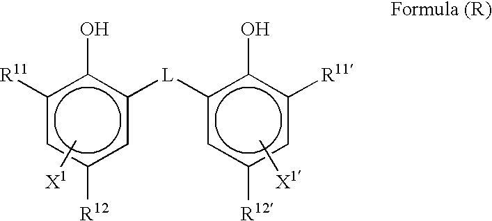
As R21 to R23, an
alkyl group,
aryl group,
alkoxy group, and aryloxy group are preferred. From the standpoint of effectiveness of the invention, it is preferred that at least one of R21 to R23 is an
alkyl or
aryl group, and it is more preferred that two or more of them are
alkyl or
aryl group. Further, in view of the availability at a reduced cost, it is preferred that R21 to R23 are of an identical group.
[0244]; and the methods described in JP-A Nos.11-98708 and 2000-347335 are also preferable. 3) Grain Size The photosensitive
silver halide grains preferably have a smaller size in order to prevent the formed images from becoming cloudy. Specifically, the size is preferably at most 0.20 μm, more preferably falling between 0.01 μm and 0.15 μm, and even more preferably between 0.02 μm and 0.12 μm. The grain size as used herein refers to the
diameter of the circular image having the same area as the
projected area of each
silver halide grain (for tabular grains, the main plane of each grain is projected to determine the
projected area of the grain). 4)
Grain Shape Silver halide grains may have various shapes including, for example, cubic grains, octahedral grains, tabular grains, spherical grains, rod-like grains, and potato-like grains. Cubic silver
halide grains are especially preferred for use in the present invention. Also preferred are roundish silver
halide grains having rounded corners. The surface index (Miller's index) of the outer surface of the photosensitive silver
halide grains for use in the present invention is not specifically limited, but it is preferred that the proportion of {100} plane, which ensures higher spectral
sensitization when it has adsorbed a color-sensitizing dye, in the outer surface is large. Preferably, the proportion of {100} plane is at least 50%, more preferably at least 65%, and even more preferably at least 80%. The Miller's index expressed by the proportion of {100} plane can be obtained according to the method described in J. Imaging Sci., written by T. Tani, 29, 165 (1985), based on the adsorption dependency of {111} plane and {100} plane for sensitizing dyes. 5) Heavy
Metal The photosensitive silver halide grains for use in the present invention may contain a
metal or
metal complex of Groups VIII to X of the
Periodic Table (including Groups I to XVIII). As the
metal or the central metal of metal complex of Groups VIII to X, preferably used is
rhodium,
ruthenium or
iridium. In the present invention, one metal complex may be used alone, or two or more metal complexes of the same species or different species of metals may be used in combination. The metal or metal complex content of the grains preferably falls between 1×10⁻⁹ mols and 1×10⁻³ mols per mol of silver. Such
heavy metals and metal complexes, and methods of adding them to silver halide grains are described in, for example, JP-A No.7-225449, JP-A No.11-65021, paragraphs
[0250]. 6)
Gelatin Various kinds of gelatins may be used for preparing the photosensitive silver halide emulsions for use in the present invention. In order to sufficiently disperse the photosensitive silver halide
emulsion in a
coating solution containing an organic silver salt, preferably used is a low-molecular
gelatin having a molecular weight of from 10,000 to 1000,000. The phthalated
gelatin is preferably used. The low-molecular
gelatin may be used when forming the silver halide grains or when dispersing the grains after the grains have been desalted. Preferably, it is used when dispersing the grains after they have been desalted. 7) Sensitizing Dye As the sensitizing dyes applicable in the invention, those dyes capable of spectrally sensitizing silver halide grains in a desired
wavelength region are advantageously selected. The sensitizing dye is adsorbed to silver halide grains having a
spectral sensitivity suitable to the spectral characteristics of an
exposure light source. Details of sensitizing dyes and methods for adding them to the photothermographic material of the present invention, reference are made to paragraphs
[0109] in JP-A No.11-65021; compounds of formula (II) in JP-A No.10-186572; dyes of formula (I) and
paragraph [0106] in JP-A No.11-119374; dyes described in U.S. Pat. Nos. 5,510,236 and 3,871,887 (Example 5); dyes described in JP-A Nos.2-96131 and 59-48753; from page 19, line 38 to page 20, line 35 in EP No.0803764A1; JP-A Nos.2001-272747, 2002-290238 and 2002-23306. These sensitizing dyes may be used herein either singly or in combination of two or more. Regarding the time at which the sensitizing dye is added to the silver halide
emulsion in the present invention, it is desirable that the sensitizing dye is added thereto after the desalting step but before the
coating step, more preferably after the desalting step but before the chemical
ripening step. The amount of the sensitizing dye to be included in the photothermographic material of the present invention varies as desired, depending on the sensitivity and the
fogging properties of the material. In general, it preferably falls between 10−6 and 1 mol, more preferably between 10−4 and 10−1 mols, per mol of the silver halide in the image-forming layer of the material. In order to improve spectral
sensitization, a supersensitizer may be used in the present invention. For the supersensitizer, for example,
usable are the compounds described in EP No.587,338, U.S. Pat. Nos. 3,877,943, 4,873,184, and JP-A Nos.5-341432, 11-109547 and 10-111543, the disclosures of which are incorporated by reference. 8) Chemical
Sensitization Preferably, the photosensitive silver halide grains for use in the present invention are chemically sensitized with, for example,
sulfur,
selenium or
tellurium. For such
sulfur,
selenium or
tellurium sensitization, any known compounds are
usable. For example, preferred are the compounds described in JP-A No.7-128768.
Tellurium sensititization is preferably conducted in the present invention, using the compounds described in JP-A No.11-65021,
paragraph  Login to View More


