Analogue regenerative transponders including regenerative transponder systems

a regenerative transponder and analog technology, applied in the field of analog regenerative transponder including regenerative transponder system, can solve the problems of reducing information bandwidth, cost and reducing complexity, and achieving results that cannot be achieved using conventional technology, and achieves reduced total system cost, wide bandwidth communication, and improved overall coverage

Inactive Publication Date: 2005-03-31
VAVIK GEIR MONSEN
View PDF20 Cites 299 Cited by
  • Summary
  • Abstract
  • Description
  • Claims
  • Application Information

AI Technical Summary

Benefits of technology

[0031] By facilitating wide bandwidth communication on global infrastructures like power grids circuits, new concepts for mobile communication and other becomes possible. As an example, the everywhere present power infrastructure allows the invention to realise a larger number of reduced area communication cells at greatly reduced total system

Problems solved by technology

This known technology works at the expense of complexity, cost and reduced information bandwidth.
Despite all improvements in digital signal processing, the attainable results will always be ultimately limited by the analogue signal processing parameters.
This type of duplex signal repetition will in most systems lead to instability and therefore cannot be realised using conventional technology.
Textbooks therefore have no solutions for this type of problem.
A typical modern problem of this kind is the up- and downstream amplification in Cable Modem systems.
Here the problem is passing two signal directions through one coaxial cable and amplifying the signals at certain intervals.
In other cable and wire based applications there simply are no analogue gain solutions when high isolation between ports cannot be realised from one reason or the other.
A typical example is a power circuit grid connection box where connections must enter and leave the power rails directly and thereby inhibit acceptable amplifier port isolation.
Similarly, in power grid transformer stations, signal leakage via the low voltage circuits, the transformer and the medium voltage circuits prevent acceptable isolation.
Using analogue gain blocks in the power grid which also can be cascaded evidently was not thought of as realistic and practicable in PLC systems.
The serious set-backs PLC access systems have suffered from the inability to produce reliable, large bandwidths and to comply with regulations demonstrate this.
That implies also a further challenge to conventional gain blocks in that the gain block must be bi-directional.
The switching nature of the signals just makes the emission problem more serious.
Long delay times are also a typical disadvantage of these systems, making them less applicable to time critical applications, like IP telephony.
PLC systems are characterized by the lack of ability to use as high a carrier frequency as the infrastructure will allow to improve emission and immunity characteristics, to enjoy the benefits of damped reflections and to reduce the in band group delay ripple.
However, this gain is usually not nearly

Method used


Image

  • Analogue regenerative transponders including regenerative transponder systems
  • Analogue regenerative transponders including regenerative transponder systems
  • Analogue regenerative transponders including regenerative transponder systems

Examples


Embodiment Construction

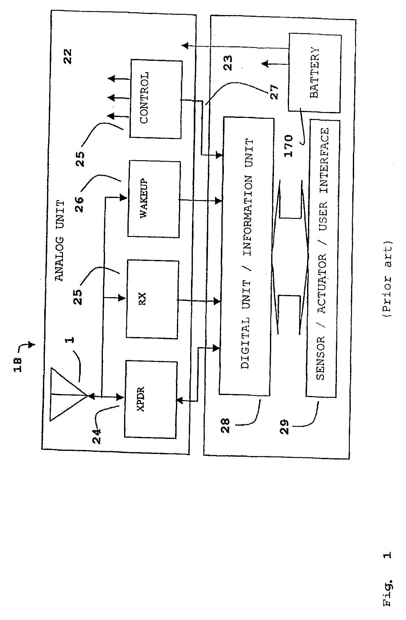
[0050] In FIG. 1 is shown a typical transponder device 18 consisting of an analogue 22 and a digital 23 unit. The analogue part has an antenna 1 and a radio frequency transponder 24. The transponder 24 may be a modulated transmitter or a transponder capable of retransmitting the incoming carrier with a modulated response from the transponder 18. It is often designed to include a down link receiver 25 and a wake up receiver 26 as well as a control unit 25. When the digital part is included in the transponder device 18 it will consist of an information unit 28 normally combined with an interface 29. The transponder device 18 also consists of a power supply most commonly made up of a battery 170.

[0051] The most important part of the transponder device 18 is the transponder 24 for up link. The down link information receiver 25 is either a separate part of the transponder device 18 or is partly integrated with the wake up receiver 26. The digital unit 23 information device 28 identifies...


PUM


Abstract

In a transponder (19) for amplification of a received signal (60) into an antenna (1), to a signal (61) for retransmission, and where the retransmitted signal (61) possibly may have information superimposed, a quenched oscillator (5) is incorporated as amplifying element. The oscillator (5) is preferably of superregenerative type and exhibits negative resistance (30) for the received signal (60). Transponders according to the present invention may be introduced as system elements in a wireless or wire based network to work as intelligent or unintelligent connections in the network. The transponders can also be used in positioning systems.

Description

INTRODUCTION [0001] The present invention concerns transponders of the general type as explained in the preamble of the appended claim 1, the application of such transponders in networks, as well as transponder systems in networks as given in the preamble of the appended claim 33. BACKGROUND [0002] In a transponder system a radio frequency signal is transmitted to a transponder, which in turn retransmits the signal, often in modulated form, that is to say with superimposed information from the transponder. The purpose of a transponder may thereby be to convey or retrieve information related to the transponder in some way. Transponders normally are not expected to relay the incoming signal only with the original information. Some transponders work indirectly, others directly. In indirect retransmission, the signal is received and retransmitted in sequence. Retransmission may be desired to take place in a frequency band different from the band for received signal. Modern digital commu...

Claims


Application Information

Patent Timeline
IPC IPC(8): H04B1/59H04B7/14
CPCH04B7/155H04B1/59
Inventor VAVIK, GEIR MONSEN
Owner VAVIK GEIR MONSEN
Why Eureka
Try Eureka