Solid oxide fuel cell system

a fuel cell and solid oxide technology, applied in the direction of electrochemical generators, sustainable manufacturing/processing, lighting and heating apparatus, etc., can solve the problems of increasing the size deteriorating cell performance, and limited components of the sofc system

Inactive Publication Date: 2005-04-28
TOKYO GAS CO LTD
View PDF7 Cites 54 Cited by
  • Summary
  • Abstract
  • Description
  • Claims
  • Application Information

AI Technical Summary

Benefits of technology

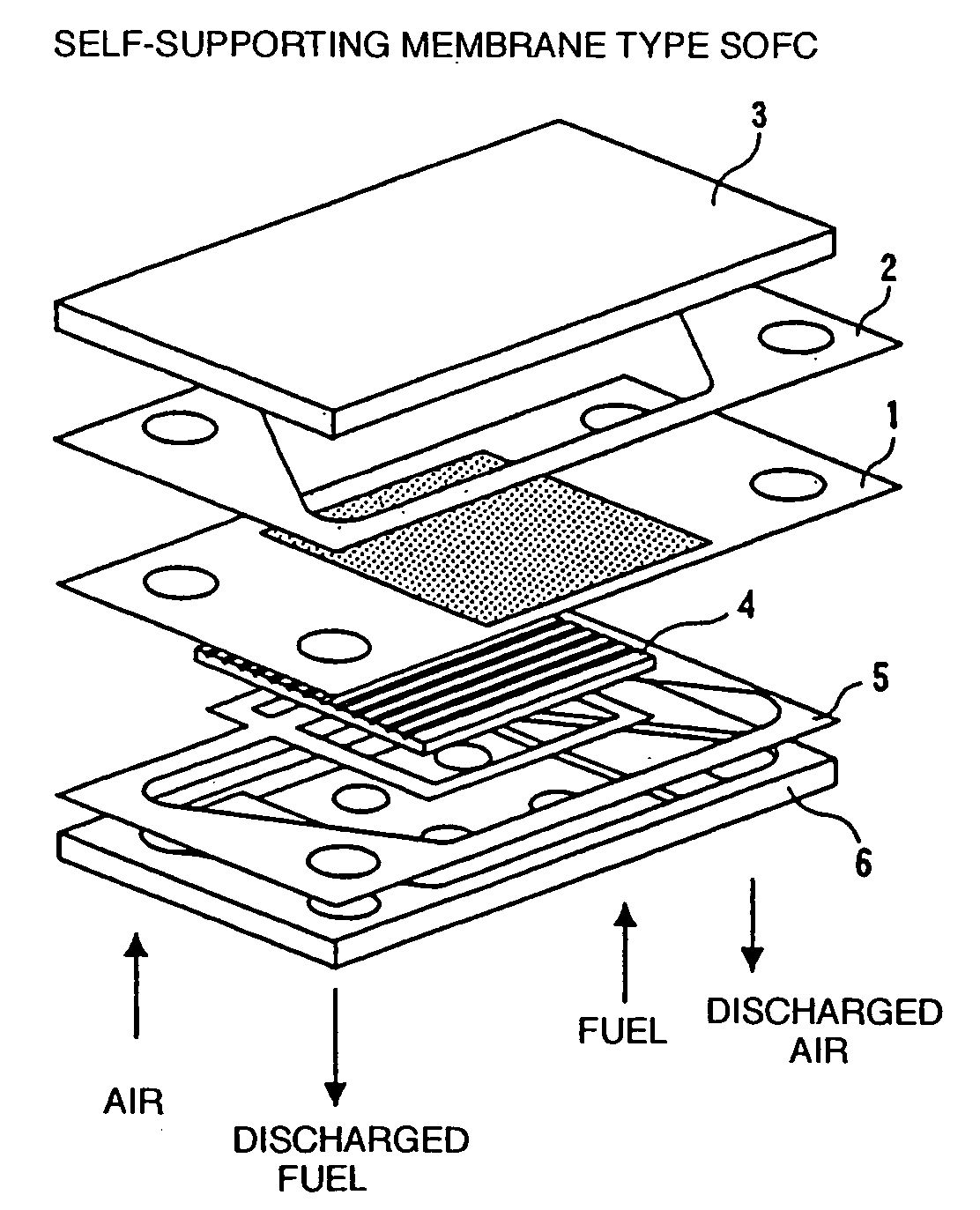
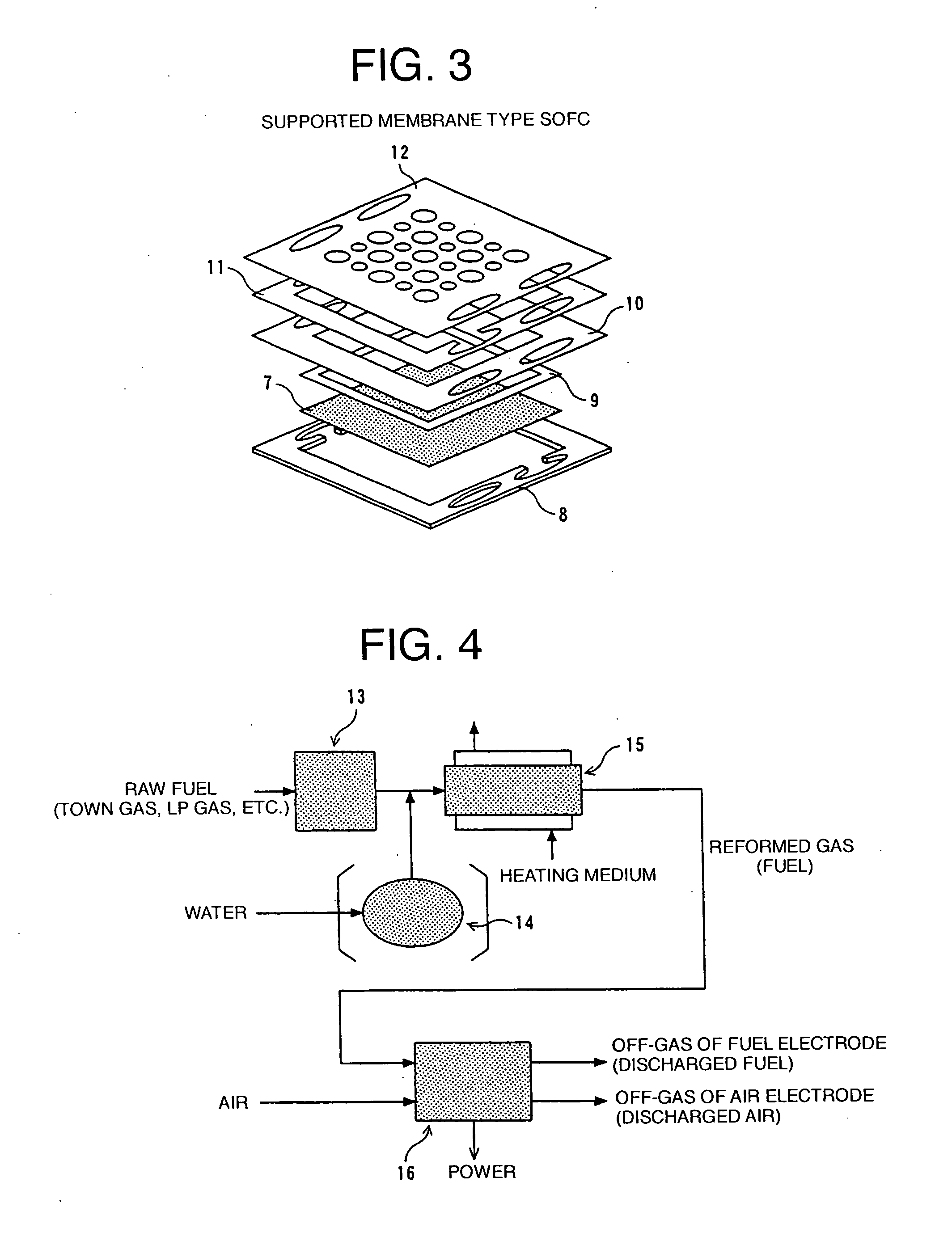
[0019] The invention provides a solid oxide fuel cell system comprising (a) a solid oxide fuel cell stack, (b) a preliminary reformer for removing hydrocarbons having two or more carbon atoms from a hydrocarbon fuel by converting the hydrocarbons having two or more carbon atoms into methane, hydrogen, and carbon monoxide, and (c) an integrated heat exchanger for catalytic combustion for heating air and / or fuel (that is, either air or fuel, or both) to be guided to the solid oxide fuel cell stack, by use of a combustion gas formed by combusting discharged fuel from the solid oxide fuel cell stack with the use of discharged air, wherein component equipment described above are disposed in an adiabatic vessel. Herein, “in an adiabatic vessel” described above means to include a case where the SOFC stack and various component equipment thereof are covered with a thermal insulating material. Further, the invention provides an integrated heat exchanger for catalytic combustion disposed in the vicinity of an SOFC stack, suitable for use in the solid oxide fuel cell system, described under items (1) to (6) below:

Problems solved by technology

Component members thereof are therefore limited to expensive heat-resistant alloys or ceramics.
In the case of the ceramics, there arise such problems as cracks occurring thereto due to differences in temperature occurring inside the stack, and so firth, while in the case of housing the stack in an adiabatic vessel, a thermal insulating material of the adiabatic vessel increases in thickness, resulting in an increase in the size of an SOFC system.
However, if the raw fuel contains hydrocarbons other than methane, that is, hydrocarbons having two or more carbon atoms, such as ethane, ethylene, propane, butane, etc., this will cause carbon to be formed on piping to the SOFC and the fuel electrode, which blocks electrochemical reaction, thereby resulting in deterioration in cell performance.
If sulfur compound is contained in the raw fuel, the fuel electrode of the SOFC will undergo poisoning caused by the sulfur compound.

Method used


Image

  • Solid oxide fuel cell system
  • Solid oxide fuel cell system
  • Solid oxide fuel cell system

Examples


embodiment 1

[0109]FIG. 23 is a longitudinal sectional view showing a configuration of a preliminary reformer by way of example. The present preliminary reformer corresponds to the preliminary reformer in the case where water is heated in the preliminary reformer to be thereby turned into the steam in the modes shown in FIGS. 5 to 7, respectively. In FIG. 23, the arrows indicate respective flow directions of fluids.

[0110] As shown in FIG. 23, cylinders 44, 45, 46, 47, 48, sequentially increasing in diameter, were disposed in multiple layers with spacing in-between. A heat exchanger (water heater) was built inside the innermost cylinder 44 in which a tubular heat exchange tube 49 disposed so as to form a coil. A reformation catalyst layer 50 was made up between the cylinder 44 surrounding the heat exchanger and the cylinder 45, and the reformation catalyst layer 50 was filled up with reformation catalysts for preliminary reformation. Reference numeral 51 denotes a water inlet conduit, and water ...

embodiment 2

[0112]FIGS. 24, 25 are schematic representations illustrating a configuration of an integrated heat exchanger for catalytic combustion, respectively, by way of example, and FIG. 24 is a longitudinal sectional view thereof while FIG. 25 is a sectional view taken on line A-A in FIG. 24. In FIG. 24, the arrows indicate respective flow directions of fluids.

[0113] As shown in FIG. 24, a first heat exchanger 59 was disposed at the center in the lower part of the integrated heat exchanger for catalytic combustion, and a second heat exchanger 60 at the center in the upper part thereof. Both the heat exchangers were plate-fin type heat exchangers built by alternately stacking tube plates and corrugate fins on top of each other. In both the heat exchangers, air to be fed to an SOFC stack was heated through indirect heat exchange. A mixture part (mixing chamber) 61 was disposed at a side part of the second heat exchanger 60, and a catalytic combustion layer 63 was disposed so as to be continu...

embodiment 3

[0121] A prototype of the supported membrane type SOFC, the preliminary reformer according to Embodiment 1 (FIG. 23), and the integrated heat exchanger for catalytic combustion according to Embodiment 2 (FIGS. 24, 25) were combined together and housed in the adiabatic vessel 30, thereby building an SOFC system for testing. For the adiabatic vessel, use was made of an adiabatic vessel with glass wool serving as a thermal insulating material 29, disposed around the adiabatic vessel. As shown in FIG. 21, the prototype of the SOFC stack 36, the integrated heat exchanger 32 for catalytic combustion, and the preliminary reformer 31 were assembled inside the adiabatic vessel 30 in sequence from the upper part to the lower part thereof.

[0122] For the raw fuel, use was made of a desulfurized town gas (for this reason, the desulfurizer 38 was not disposed). The fuel obtained by bringing in the raw fuel from the inlet pipe 57 via the raw fuel blower 37 and reforming the same in the preliminar...


PUM

PropertyMeasurementUnit
thicknessaaaaaaaaaa
temperatureaaaaaaaaaa

Abstract

There are provided a solid oxide fuel cell system comprising (a) a solid oxide fuel cell stack, (b) a preliminary reformer for removing hydrocarbons having two or more carbon atoms from a hydrocarbon fuel by converting the hydrocarbons having two or more carbon atoms into methane, hydrogen, and carbon monoxide, and (c) an integrated heat exchanger for catalytic combustion for heating either air or fuel, or both the air and fuel, to be guided to the solid oxide fuel cell stack, by use of a combustion gas formed by combusting discharged fuel with the use of discharged air, wherein component equipment described above are disposed in an adiabatic vessel and the integrated heat exchanger for catalytic combustion for use in the solid oxide fuel cell system. With the invention, an advantage of the preliminary reformer in combination with that of the integrated heat exchanger for catalytic combustion can be obtained, and heat loss of the SOFC system is eliminated or reduced as much as possible. In addition, with the integrated heat exchanger for catalytic combustion according to the invention, since air and/or fuel, to be fed to the SOFC stack, can be heated by controlling the maximum temperature achieved thereof, it is quite useful as an heat exchanger for an SOFC with operation temperature on the order of 850° C. or lower, particularly, for a supported membrane type SOFC, and further, the same is quite useful in making up an SOFC system because an inexpensive material can be used as a constituent material of a component equipment of the system, the system in whole can be reduced in size, and so forth.

Description

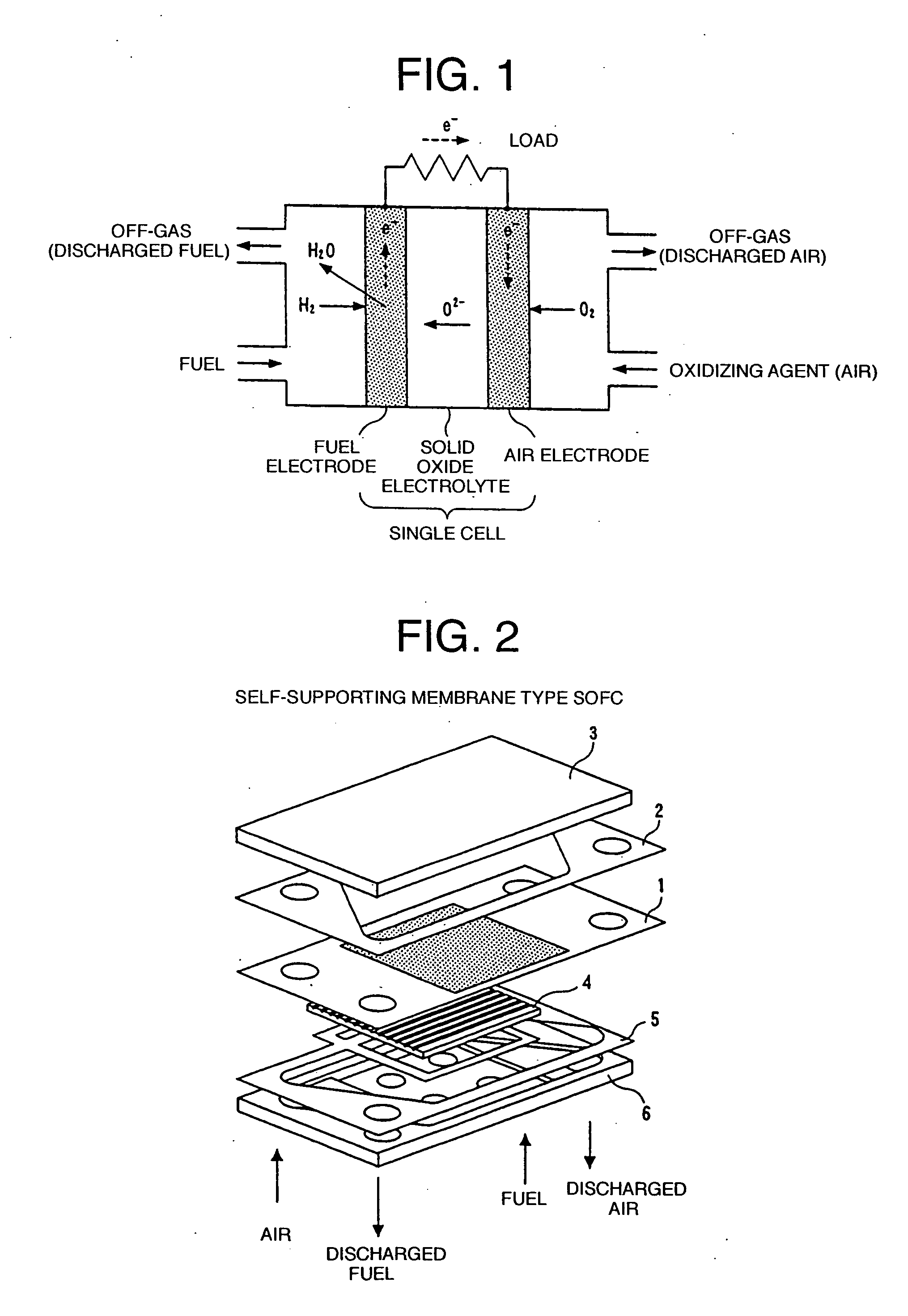
TECHNICAL FIELD [0001] The invention relates to a solid oxide fuel cell system comprising a solid oxide fuel cell stack, a preliminary reformer, and an integrated heat exchanger for catalytic combustion, housed in an adiabatic vessel, and the integrated heat exchanger for catalytic combustion for use in the same. BACKGROUND TECHNOLOGY [0002] A solid oxide fuel cell (Solid Oxide Fuel Cell: hereinafter referred to as an SOFC as necessary) is characterized in that an oxide ion (O2−) conductor is used as a solid electrolyte and is made up of a fuel electrode and an oxygen electrode, disposed in such a way as to sandwich a solid oxide electrolyte therebetween. At the time of operation, electrochemical reaction is caused to occur by feeding fuel toward the fuel electrode, and an oxidizing agent toward the oxygen electrode, thereby extracting electric power. As the oxidizing agent fed toward the oxygen electrode, use is made of an oxygen-enriched air, oxygen, etc. besides air, however, des...

Claims


Application Information

Patent Timeline
Patent Type & Authority Applications(United States)
IPC IPC(8): C01B3/34H01M8/04H01M8/06H01M8/24
CPCC01B3/34C01B2203/0227C01B2203/066C01B2203/0811C01B2203/0822C01B2203/0827Y02E60/525H01M8/04074H01M8/0612H01M8/0618H01M8/2425H01M2008/1293Y02E60/50H01M8/04022Y02P20/10
Inventor OGIWARA, TAKASHIMATSUZAKI, YOSHIOYASUDA, ISAMUITO, KENTARO
Owner TOKYO GAS CO LTD
Why Eureka
Try Eureka