

Image forming method using toner
a toner and image technology, applied in the field of image forming methods, can solve the problems of insufficient fixation of toner images, deterioration of heat response of films, and rapid fall of outer surfaces of films, etc., and achieve the effect of high quality
- Summary
- Abstract
- Description
- Claims
- Application Information
AI Technical Summary
Benefits of technology
Problems solved by technology
Method used
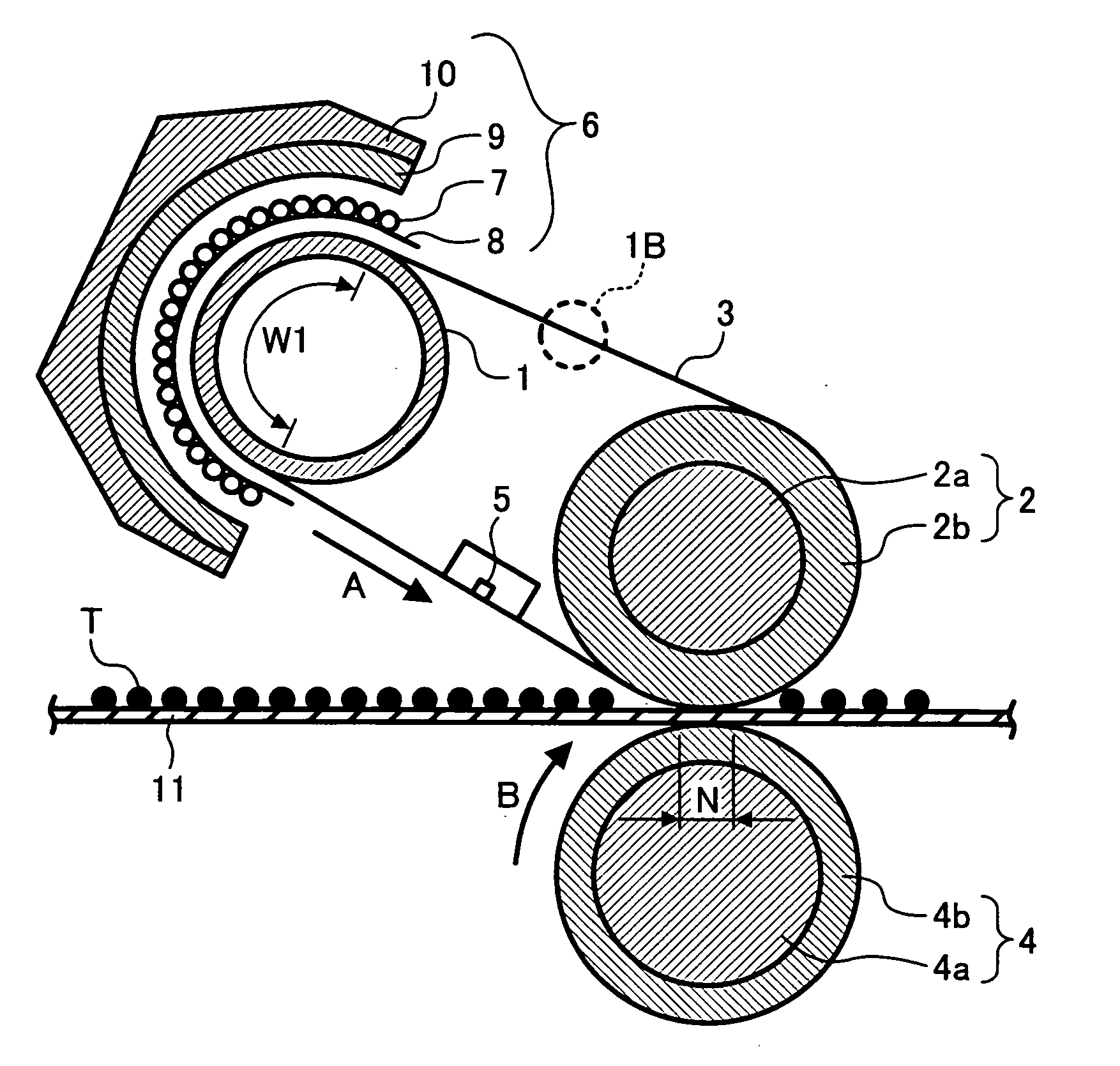
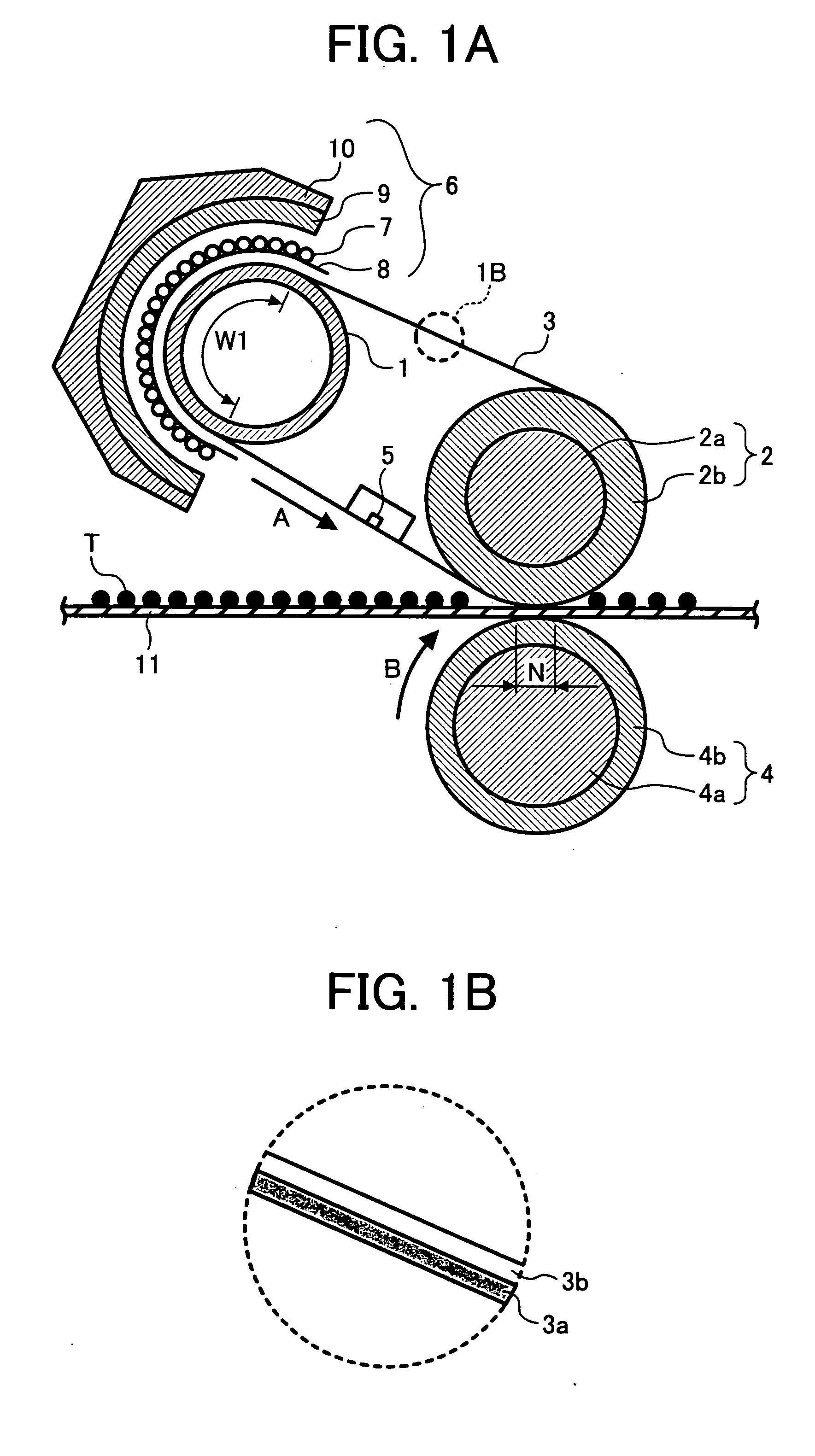
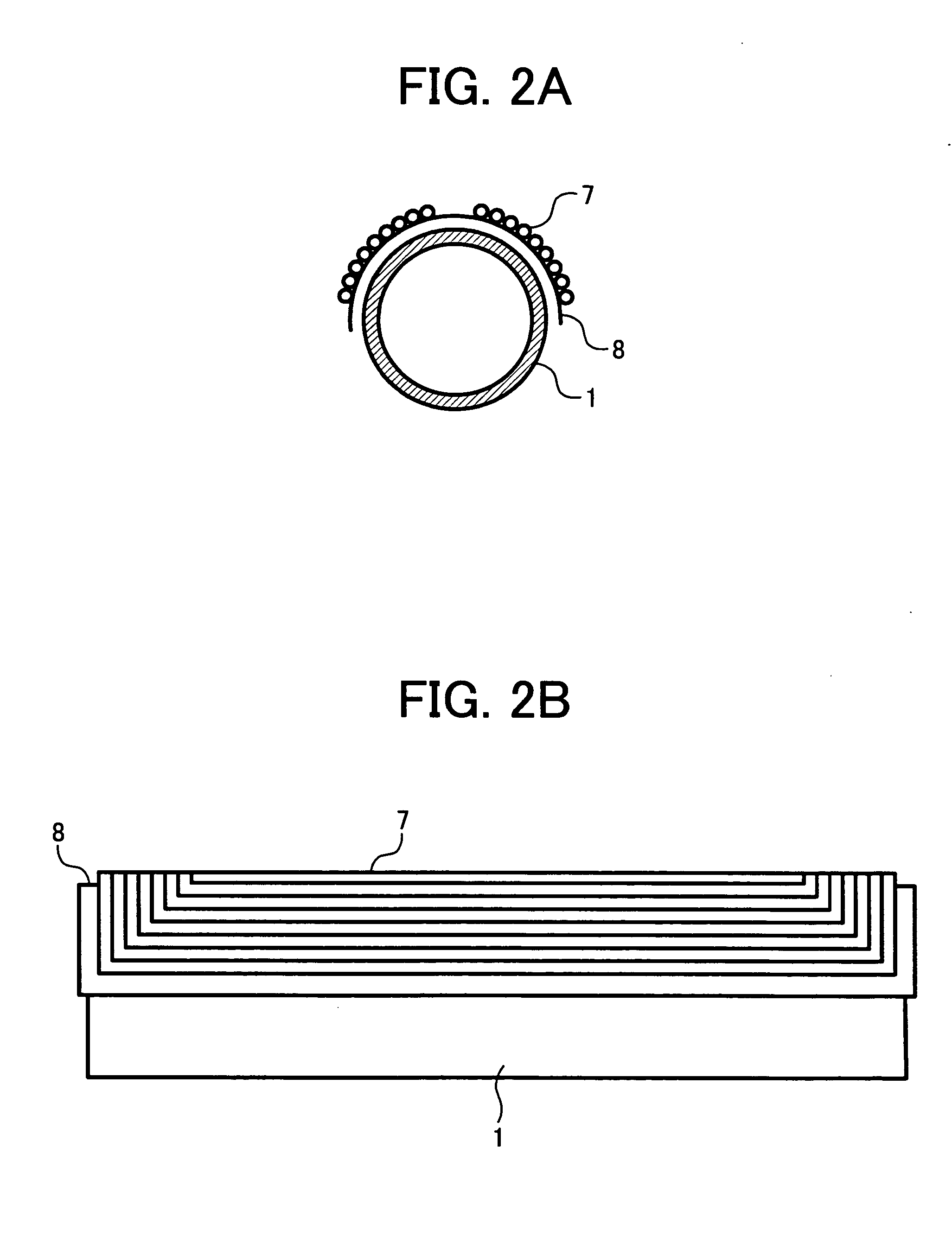
Image

Examples
example 1
Preparation of Particulate Resin Dispersion
[0202] In a reaction vessel equipped with a stirrer and a thermometer, 683 parts of water, 15 parts of a sodium salt of sulfate of an ethylene oxide adduct of methacrylic acid (ELEMINOL RS-30 from Sanyo Chemical Industries Ltd.), 83 parts of styrene, 83 parts of methacrylic acid, 110 parts of butyl acrylate, and 1 part of ammonium persulfate were mixed. The mixture was agitated for 15 minutes while the stirrer was rotated at a revolution of 400 rpm. As a result, a milky emulsion was prepared. Then the emulsion was heated to 75° C. to react the monomers for 5 hours.
[0203] Further, 30 parts of a 1% aqueous solution of ammonium persulfate were added thereto, and the mixture was aged for 5 hours at 75° C. Thus, an aqueous dispersion of a vinyl resin (i.e., a copolymer of styrene / methacrylic acid / butyl acrylate / sodium salt of sulfate of ethylene oxide adduct of methacrylic acid, hereinafter referred to as particulate resin dispersion (1)) was...
example 2
[0234] The procedure for preparation of the toner particles in Example 1 was repeated except that the emulsification, aging, and solvent removing processes were changed as follows.
Emulsification, Aging and Solvent Removal
[0235] The emulsion 1 was fed into a container equipped with a stirrer having paddles and a thermometer, and the emulsion was aged for 30 minutes at 32° C. while agitated at a revolution of 200 rpm. Then the emulsion was heated for 8 hours at 30° C. to remove the organic solvent (ethylacetate) from the emulsion. Thus, a dispersion 2 was prepared. The particles dispersed in the dispersion 2 have a volume average particle diameter of 5.56 μm and a number average particle diameter of 5.19 μm, which was measured with MULTISIZER II.
Washing and Drying
[0236] The thus prepared dispersion 2 was washed and dried in the same manner as that in Example 1.
[0237] Thus, toner particles 2 were prepared.
example 3
[0238] The procedure for preparation of the toner in Example 1 was repeated except that the emulsification, aging, and solvent removing processes were changed as follows.
Emulsification, Aging and Solvent Removal
[0239] The emulsion 1 was fed into a container equipped with a stirrer having paddles and a thermometer, and the emulsion was aged for 4 hours at 25° C. while agitated at a revolution of 180 rpm. Then the emulsion was heated for 8 hours at 30 C. to remove the organic solvent (ethyl acetate) from the emulsion. Thus, a dispersion 3 was prepared. The particles dispersed in the dispersion 3 have a volume average particle diameter of 6.22 μm and a number average particle diameter of 5.90 μm, which was measured with MULTISIZER II.
Washing and Drying
[0240] The thus prepared dispersion 3 was washed and dried in the same manner as that in Example 1.
[0241] Thus, toner particles 3 were prepared.
PUM
| Property | Measurement | Unit |
|---|---|---|
| thickness | aaaaa | aaaaa |
| acid value | aaaaa | aaaaa |
| Tg | aaaaa | aaaaa |
Abstract
Description
Claims
Application Information