Gas decomposing unit, electrode for a fuel cell, and method of manufacturing the gas decomposing unit

a fuel cell and gas decomposing technology, applied in the direction of organic compounds/hydrides/coordination complexes, cell components, physical/chemical process catalysts, etc., can solve the problems of deteriorating catalytic activity, unsatisfactory electric conductivity, and place limitations on the use of electrodes, so as to reduce the length of the cross-linked site between carbon nanotubes and stable chemical structure

Inactive Publication Date: 2005-04-28
FUJIFILM BUSINESS INNOVATION CORP
View PDF13 Cites 23 Cited by
  • Summary
  • Abstract
  • Description
  • Claims
  • Application Information

AI Technical Summary

Benefits of technology

[0051] With this method, the size of the cross-linked site, which bonds the carbon nanotubes together, becomes constant depending on the functional group to be bonded. A carbon nanotube has an extremely stable chemical structure, so that there is a low possibility that functional groups or the like excluding the functional groups intended for a modification are bonded to the carbon nanotube. When chemically bonding the functional groups together, the designed structure of the cross-linked site can be obtained, providing a homogeneous carbon nanotube structure.
[0052] Further, functional groups are chemically bonded together and thus the length of the cross-linked site between the carbon nanotubes can be shortened compared to the case of cross-linking the functional groups together using a cross-linking agent. Therefore, the carbon nanotube structure becomes dense, and effects peculiar to carbon nanotubes are easily obtained.

Problems solved by technology

The variations place limitations on the use of the electrode.
However, in this case, a supported catalyst is embedded in the resin to provide extremely poor contact between a reaction gas and the catalyst, thereby resulting in deteriorated catalytic activity.
In addition, if carbon nanotubes are isolated from each other in the binder, electric conductivity is unsatisfactory.
Therefore, it becomes difficult to apply the carbon nanotubes for an electrode for a fuel cell.

Method used


Image

  • Gas decomposing unit, electrode for a fuel cell, and method of manufacturing the gas decomposing unit
  • Gas decomposing unit, electrode for a fuel cell, and method of manufacturing the gas decomposing unit
  • Gas decomposing unit, electrode for a fuel cell, and method of manufacturing the gas decomposing unit

Examples


examples

[0176] A more specific description of the present invention is given below through Examples. However, the present invention is not limited to the following example.

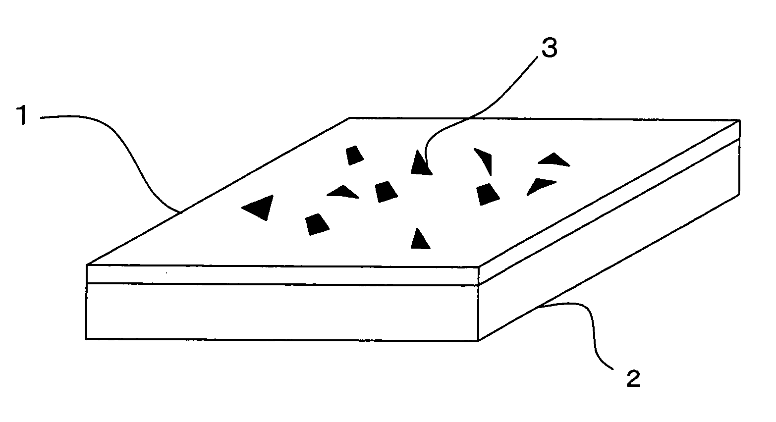
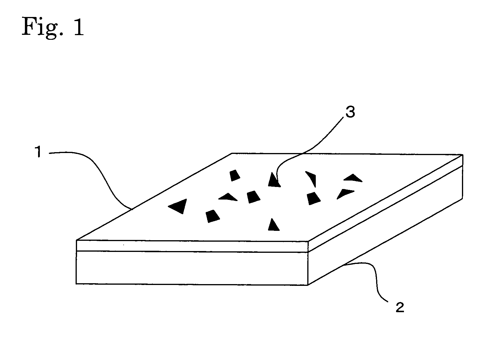
[0177] A gas decomposing unit was manufactured through a flow of the method of manufacturing a gas decomposing unit shown in FIG. 1. It should be noted that reference numerals in FIG. 1 may be used in the description of this example.

(A) Applying Step

(A-1) Preparation of Cross-Linking Application Solution (Addition Step)

(1) Addition of Carboxyl Group . . . Synthesis of Carbon Nanotube Carboxylic Acid

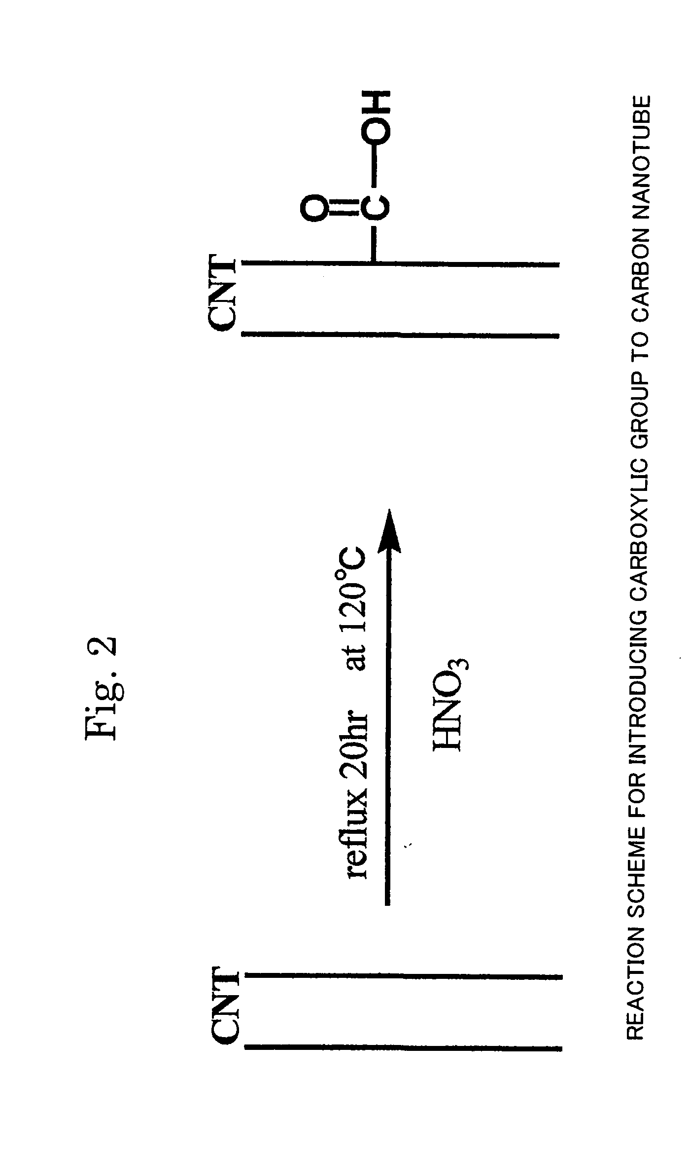
[0178] 30 mg of multi-wall carbon nanotube powder (purity: 90%, average diameter: 30 nm, average length: 3 μm, available from Science Laboratory Inc.) were added to 20 ml of concentrated nitric acid (a 60 mass % aqueous solution, available from KANTO KAGAKU) for reflux at 120° C. for 20 hours to synthesize a carbon nanotube carboxylic acid. A reaction scheme of the above is shown in FIG. 3. In FIG. 3, a carbon nanotube ...

verification experiment

(Verification Experiment)

[0187] Platinum fine particles were deposited by ion sputtering on the nanotube structure obtained in Example 1 to prepare a gas decomposing unit. It should be noted that a platinum fine particle is generally used as a gas decomposing catalyst having an action of decomposing NOx in an exhaust gas. The surface of the resultant catalyst was observed with an electron microscope. As shown in FIG. 5, this observation confirmed that a nanotube structure layer was evenly formed on the molecular sieve surface having a complex shape. In addition, an energy dispersive X-ray analyzer confirmed that the platinum fine particles were supported on the nanotube.

[0188] According to the present invention, a gas decomposing catalyst is supported on a structured carbon nanotube structure, so that the carbon nanotube structure can be stably used as a gas decomposing unit. In addition, if the carbon nanotube structure is used as an electrode as well, excellent electric conductiv...


PUM

PropertyMeasurementUnit
diameteraaaaaaaaaa
Young's moduliaaaaaaaaaa
diameteraaaaaaaaaa

Abstract

Provided are a gas decomposing unit and an electrode for a fuel cell capable of stably supporting a gas decomposing catalyst. A gas decomposing unit and an electrode for a fuel cell each including: a carbon nanotube structure having a mesh structure in which functional groups bonded to plural carbon nanotubes are chemically bonded to mutually cross-link the plural carbon nanotubes; and a gas decomposing catalyst supported on the carbon nanotube structure. A method of manufacturing a gas decomposing unit characterized by including: an applying step of applying, to the surface of a substrate, a solution containing plural carbon nanotubes to which functional groups are bonded; a cross-linking step of chemically bonding the functional groups to build a mesh structure in which the plural carbon nanotubes mutually cross-link; and a supporting step of forming the carbon nanotube structure supporting a gas decomposing catalyst.

Description

FIELD OF THE INVENTION AND RELATED ART STATEMENT [0001] The present invention relates to a gas decomposing unit using a carbon nanotube structure, an electrode for a fuel cell, and a method of manufacturing the gas decomposing unit. [0002] Carbon nanotubes (CNTs), with their unique shapes and characteristics, are being considered for various applications. A carbon nanotube has a tubular shape of one-dimensional nature which is obtained by rolling one or more graphene sheets composed of six-membered rings of carbon atoms into a tube. A carbon nanotube which is formed from one graphene sheet is called a single-wall nanotube (SWNT) while a carbon nanotube which is formed from plural graphene sheets is called a multi-wall nanotube (MWNT). SWNTs are about 1 nm in diameter whereas multi-wall carbon nanotubes measure several tens nm in diameter, and both are far thinner than their predecessors, which are called carbon fibers. [0003] One of the characteristics of carbon nanotubes resides in...

Claims


Application Information

Patent Timeline
Patent Type & Authority Applications(United States)
IPC IPC(8): B82B1/00B01J21/18B01J23/16B01J23/38B01J23/42B01J31/28B01J37/34B82B3/00C01B31/02H01M4/96
CPCB01D2255/806B01D2258/0208B01J21/18B01J21/185B82Y30/00B01J23/38B01J23/42B01J37/347B01J23/16
Inventor KISHI, KENTAROANAZAWA, KAZUNORIMANABE, CHIKARAHIRAKATA, MASAKISHIGEMATSU, TAISHIWATANABE, MIHOWATANABE, HIROYUKIISOZAKI, TAKASHIOOMA, SHIGEKIOKADA, SHINSUKE
Owner FUJIFILM BUSINESS INNOVATION CORP
Why Eureka
Try Eureka