
Optical fibers made from multicomponent glass

a technology of optical fibers and glass, applied in the direction of clad optical fibres, glass making apparatus, instruments, etc., can solve the problems of high raw materials for melting this type of core glass, significant manufacturing costs of these fibers and/or light guides, and noticeable yellow tint of light exiting from light guides

Inactive Publication Date: 2005-05-12
SCHOTT AG
View PDF9 Cites 10 Cited by
  • Summary
  • Abstract
  • Description
  • Claims
  • Application Information

AI Technical Summary

Benefits of technology

[0026] good drawing properties, good drawability, i.e. without a tendency to crystallize or have boundary surface reactions, during manufacture, and
[0038] Most of the glasses described there are characterized by a highly pure transmission and good color neutrality. Besides these optical properties the glasses also have good crystallization stability and meltability. These properties allow these glasses to be considered as possible core glass candidates for optical stepped optical fibers, in so far as a suitable compatible cladding glass can be found.
[0051] In the rod-tube method a cylindrical rod made from a high index of refraction glass and the tube made from low index of refraction cladding glass surrounding it are heated in a cylindrical oven to a temperature corresponding to a viscosity of about 104 to 103 dPas. Core glass and cladding glass melt to form a so-called drawing bulb, from which the optical fiber is drawn. The fiber diameter depends on the ratio of the fiber drawing speed to the guidance speed of the rod-tube system and the diameter of the core rod and tube. Special care is taken in this process so that the core rod surface and the tube inner surface are extremely clean and free of any dirt and particles, so that they can melt to form as ideal trouble-free boundary surface as possible. Similarly it has proven advantageous when the outer diameter of the core rod and the inner diameter of the tube differ by only a few tenths of a mm, so that a uniform fault-free drawing bulb can form.

Problems solved by technology

The raw materials for melting this sort of core glass are very expensive because of the required high purity, which can lead to considerable manufacturing cost for these fibers and / or the light guides made from them.
These color shifts can cause a noticeable yellow tint to the light exiting from the light guide.
Above all this is troublesome in fields, which require color neutral image reproduction, such as in the medical endoscopy with photographic image documentation for differentiation of e.g. malignant from healthy tissue.
These contact reactions and crystallization may interfere with the total reflection of the light guided through it and thus may make the fiber unsuitable for the applications requiring light guidance with low attenuation.
Moreover the mechanical strength of the optical fiber may be negatively impaired by crystallization.
In contrast to that it has several disadvantages including average to poor attenuation (≧200 to 300 dB / km) and comparatively poor color shifting, chiefly caused by Pb-self-absorption (blue edge of the visible spectrum) as well as introduced impurities of strongly colored elements, such as chromium and nickel.
Furthermore lead is rejected more and more as environmentally unfriendly and loading the environment.
Thus in specific application areas either this fiber system is used with limitations or not at all.
However these glasses provide glass fibers with a generally small aperture (NA) and a not very high chemical resistance.
This latter disadvantage requires that the fibers are provided with a plastic jacket immediately during their manufacture after the drawing step, e.g. from the nozzle of a double crucible, as a protection against possible chemical reaction and / or mechanical action.
Furthermore the very low attenuation is obtained by using more highly pure and thus even more expensive raw materials.
These latter aspects, i.e. high manufacturing cost and the plastic jacket, make the use of this fiber system as a fiber bundle for wide applications practically impossible.
However these advantages are accompanied by a very high cost as its most serious disadvantage.
Pure quartz material is extremely expensive because of its high processing temperatures.
An expensive dosing process, the so-called preform, is required, in which the required index of refraction reduction of the pure quartz is obtained by introducing fluorine into the surface, which is necessary for optical isolation for light transmission in the finished fiber.

Method used


Image

  • Optical fibers made from multicomponent glass

Examples


embodiment 1

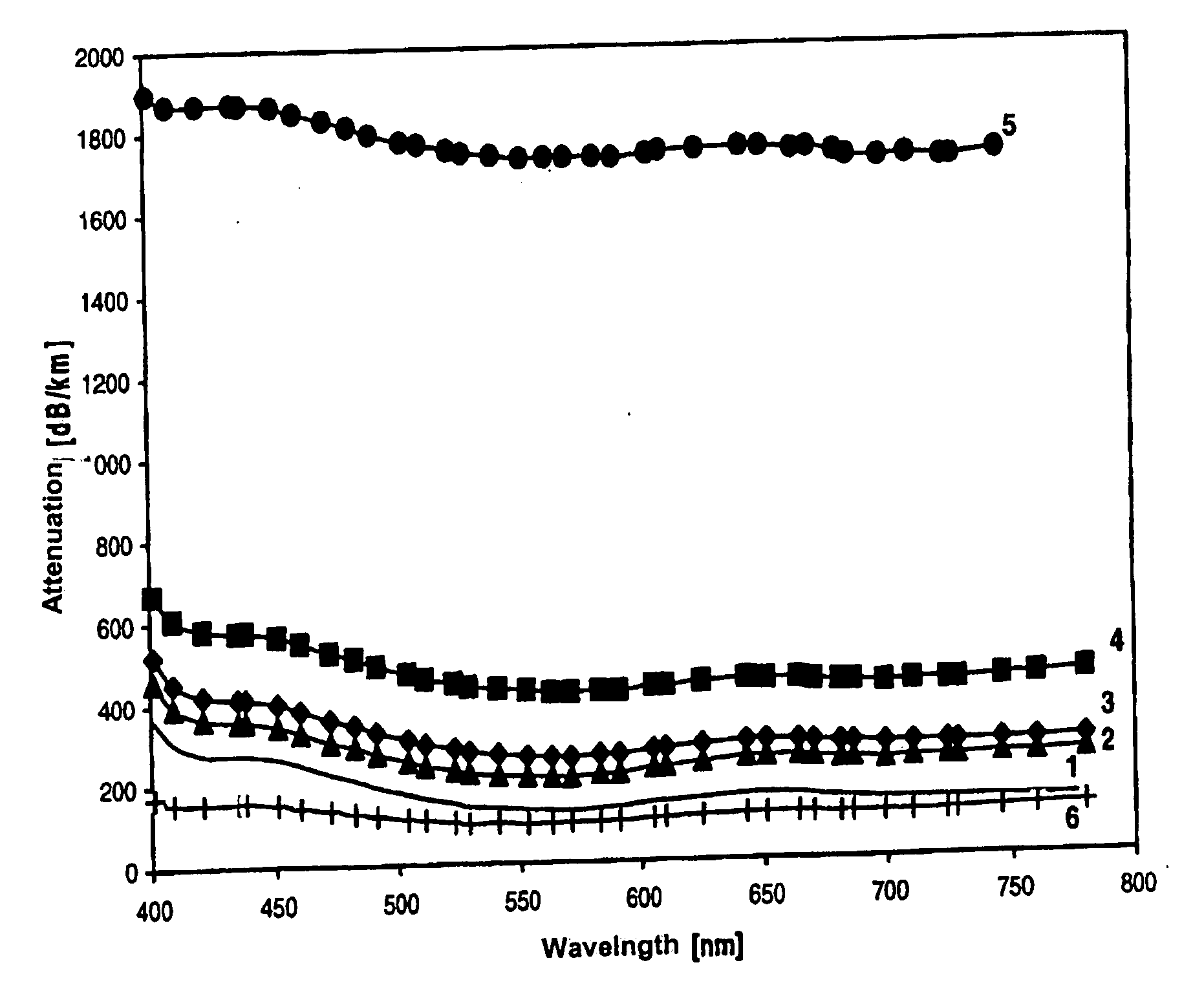
[0060] In a first series of experiments different varieties of core glass were drawn to form optical fibers with only one cladding glass, the alkali borosilicate glass according to Table II, cladding glass embodiment 1, which has proven to be especially advantageous. The results for the optical fiber made in these experiments for a total number of 8 trial core glass compositions are tabulated in Table I.

[0061] For the case of an optical fiber required to have a numerical aperture NA≧0.50, core glass embodiment 1 has the absolutely lowest attenuation level (80 dB / km at 553 nm when the raw materials employed have very high purity). It contains only 3.5% PbO and had a numerical aperture of 0.522 with the alkali borosilicate glass type 1.

[0062] Core glass compositions with lower PbO content, e.g. 1.3%, have poorer attenuation and exhibit starting crystallization. When the PbO content is greater than 3.5% indeed good drawability is guaranteed (core glass embodiments 3 and 4), generally ...

first embodiment

[0068] The last column of Table I includes the glass composition of a conventional light flint glass with very good transmission with associated attenuation values. Table I shows that the first embodiment according to the invention has an attenuation that is almost about a factor of 3 less than the attenuation of the light flint glass of the prior art, almost the same numerical aperture NA, but a factor of 10 less PbO content.

embodiment 8

[0069] Even the lead-free embodiment 8 of Table I still has a factor of greater than 2 less attenuation than that of the conventional flint glass at 553 nm. In practical applications this means that the optical fiber made from the core glass / cladding glass compositions according to the invention can transmit light over more than twice to three times the distance that a conventional optical fiber made with the light flint glass can.

[0070] Conversely the cross-sectional area of a light guide transmitting light can be reduced for the same transmission distance and the same total intensity of transmitted light when the optical fibers according to the invention with the lower attenuation are used.

[0071] An example for the case of an optimum core glass embodiment 1 (see Table I, 80 dB / km) in comparison to conventional light flint glass (see last column, 226 dB / km) for a wavelength λ=553 and a transmission distance of 20 m should illustrate this latter result. In this case only half the b...


PUM

PropertyMeasurementUnit
distancesaaaaaaaaaa
distancesaaaaaaaaaa
outer diameteraaaaaaaaaa

Abstract

The stepped optical fiber has a core glass member and a surrounding cladding glass member. It has a high numerical aperture (NA)≧0.50. The core glass member preferably has a zinc-containing composition including, in % by weight, SiO2, 42 to 53; ZnO, 16 to 38; PbO, 1 to 20; Na2O, <14; K2O, <12; with a sum of ZnO and PbO≧30 and a sum of Na2O and K2O is ≧2. The cladding glass composition, which is compatible with this core glass, includes, in percent by weight, SiO2, 60 to 72; B2O3, <20; Al2O3, <10; Na2O, <18; and K2O, <15. The resulting optical fiber has low attenuation, very neutral color transmission and low manufacturing costs. Other cladding glass compositions resulted in considerably poorer properties with too much crystallization at the core glass boundary layer. Environmentally-friendly, lead-free embodiments of the core glass were also prepared having even lower aperture values of ≧0.48.

Description

BACKGROUND OF THE INVENTION [0001] 1. Field of the Invention [0002] The invention relates to a stepped optical fiber, which consists of multicomponent glass and comprises a core glass member and a cladding glass member completely surrounding the core glass member around its peripheral wall. It also relates to the use of this sort of stepped optical fiber. [0003] 2. Description of the Related Art [0004] Generally a glass fiber or optical fiber for light transmission is made from a highly refractive core glass member and a cladding glass member surrounding it, which has a lower index of refraction than the core glass. A light transmitting glass body in fiber form, in which the index of refraction is constant across the cross-section of the core glass member, is called a stepped optical fiber. A glass fiber of this type transmits light, which is coupled into one end of the optical fiber, to the other end of the optical fiber. The light is completely reflected (total reflection) at the ...

Claims


Application Information

Patent Timeline
Patent Type & Authority Applications(United States)
IPC IPC(8): C03B37/00C03C3/078G02B6/02C03C3/083C03C3/085C03C3/087C03C3/089C03C3/091C03C3/093C03C3/102C03C3/105C03C3/108C03C3/112C03C3/115C03C3/118C03C13/04
CPCC03C13/046
Inventor DOMRES, RALFGEHENN, NORBERT WOLFRAMKOLBERG, UWEKROLLA, GEORGLENTES, FRANK THOMAS
Owner SCHOTT AG
Learn More