Exposure apparatus and method of measuring mueller matrix of optical system of exposure apparatus

a technology of optical system and exposure apparatus, which is applied in the direction of optical radiation measurement, instruments, polarising elements, etc., can solve the problems of reducing coherence capability, large birefringence, and method is not suitable to express optical birefringen

Inactive Publication Date: 2005-05-19
KK TOSHIBA
View PDF5 Cites 20 Cited by
  • Summary
  • Abstract
  • Description
  • Claims
  • Application Information

AI Technical Summary

Problems solved by technology

The fluorite, however, has a large birefringence, and may generate wave-front aberration or divide the wave front in two to reduce the capability of coherency, depending on the polarization direction of the incident light.
This method is not suitable to express the birefringence of an optical system with a plurality of optical members having curved surfaces (such as lenses).
Jones Matrix can only handle the completely polarized light beam (including no non-polariz

Method used


Image

  • Exposure apparatus and method of measuring mueller matrix of optical system of exposure apparatus
  • Exposure apparatus and method of measuring mueller matrix of optical system of exposure apparatus
  • Exposure apparatus and method of measuring mueller matrix of optical system of exposure apparatus

Examples


first embodiment

The First Embodiment

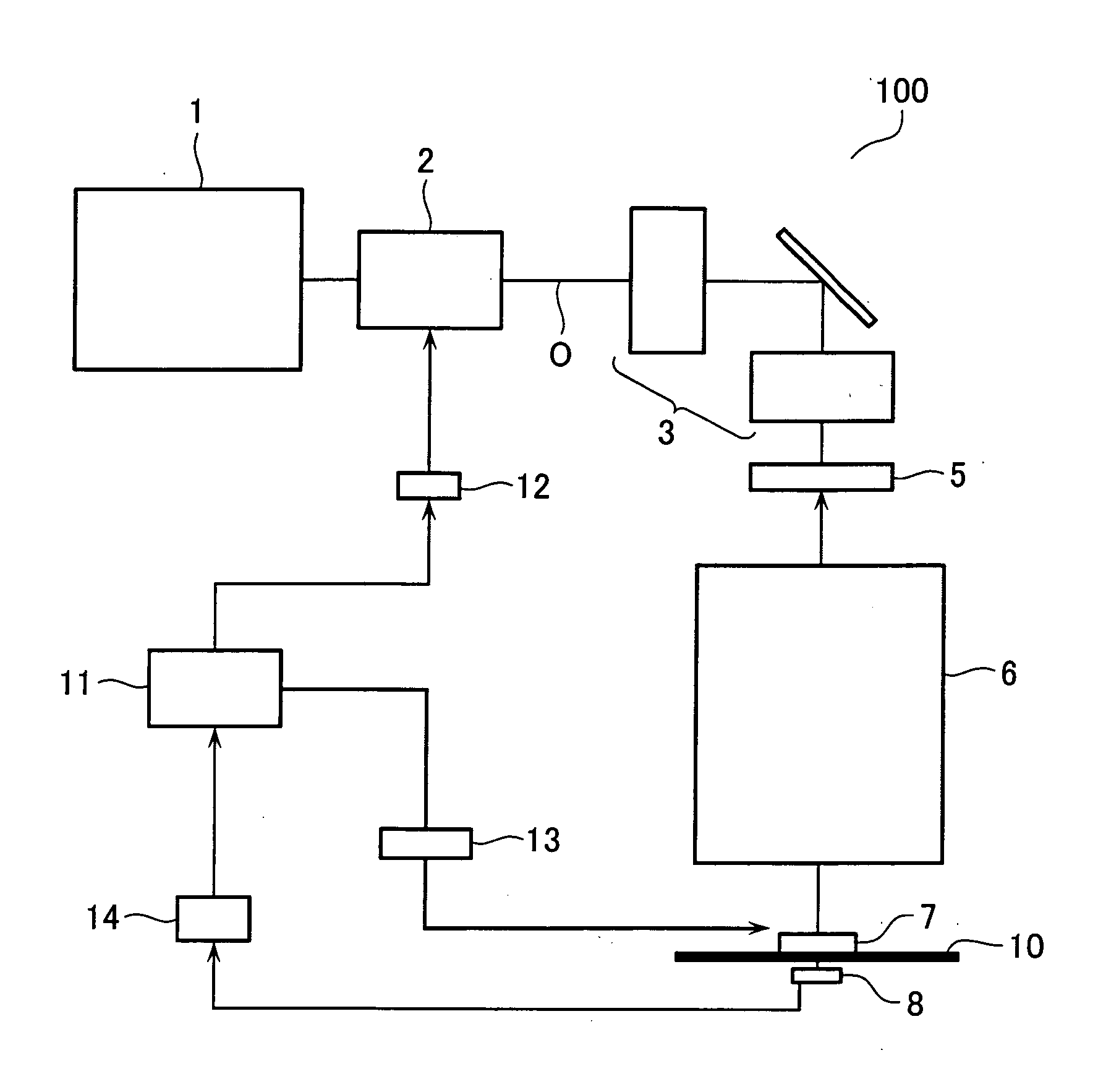
[0027]FIG. 1 shows a configuration of the exposure apparatus 100 according to the first embodiment of the present invention.

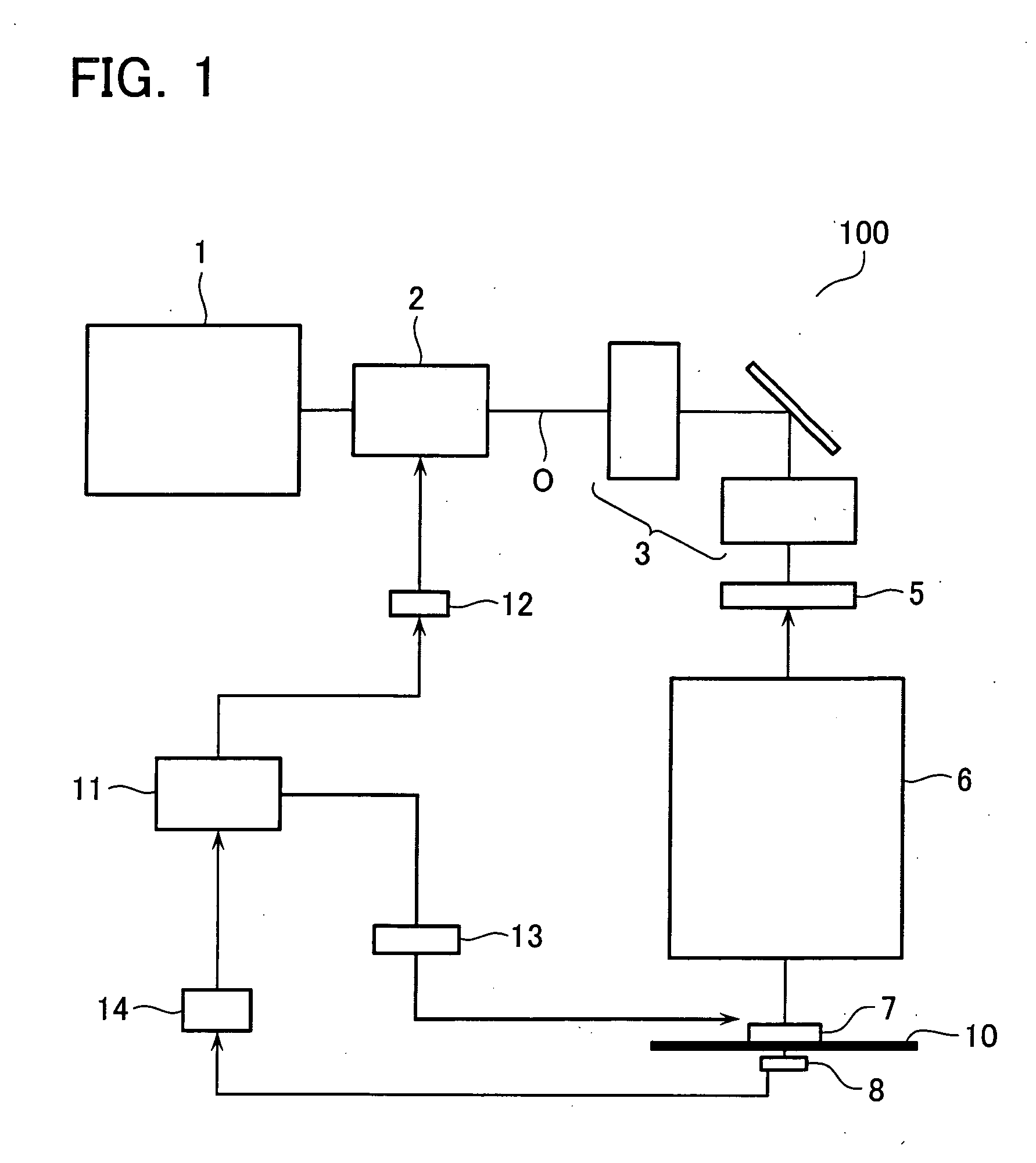
[0028] As shown in FIG. 1, this exposure apparatus 100 comprises a light source system 1, the first polarization conversion system 2, an illumination optical system 3, a photomask 5, a projection optical system 6, the second polarization conversion system 7, a photodetector 8, an arithmetic controller 11, a driver 12, a driver 13, and an A / D converter 14. In FIG. 1, the 10 depicts an imaging surface at which an object to be exposed such as a wafer is mounted. The light source system 1, such as a laser light source system, emits exposure light that has a predetermined wavelength and is polarized in a predetermined direction. The light source system 1 is here assumed to emit exposure light that is linearly polarized in a horizontal direction, i.e., in a 0 degrees direction. The illumination optical system 3, photomask 5, and projection optica...

second embodiment

The Second Embodiment

[0055] The second embodiment of the present invention will now be described.

[0056] The first embodiment measures Mueller matrix of the projection optical system 6 along the optical axis O. The second embodiment measures Mueller Matrix distribution in the pupil in the projection optical system 6 by emitting light in various directions in the pupil of the projection optical system 6 through a photomask 5 including a diffraction grating pattern with different periods and directions.

[0057] The converted polarized light beam (S′) is thus incident at an angle even on the quarter-wave plate 71. The quarter-wave plate may generally have different retardation depending on the incidence angle of the incident light. For the converted polarized light beam (S′) incident on the quarter-wave plate 71 at an angle, the quarter-wave plate 71 thus needs to be handled as a general linear polarizer. In this embodiment, the s#3#′ of the elements of Stokes parameters of the converte...

third embodiment

The Third Embodiment

[0065] The third embodiment of the present invention will now be described with reference to FIG. 7.

[0066] The first and second embodiments measure Mueller matrix of the projection optical system 6 on the assumption that the photomask 5 has no polarization characteristics. The photomask, however, may have birefringence during a process such as polishing, or may generate stress birefringence when being fixed on the exposure apparatus. In this embodiment, therefore, the photomask 5 with such polarization characteristics is considered as the linear phase retarder and its Mueller Matrix (R#&delta upper&&theta&#) is calculated separately from the projection optical system 6.

[0067] To calculate Mueller Matrix (R#&delta upper&&theta&#), this embodiment has the linear polarizer 15 disposed downstream of the photomask 5, more specifically between the photomask 5 and the projection optical system 6, as shown in FIG. 7. This linear polarizer 15 can be inserted at two azim...


PUM


Abstract

A method is provided for measuring Mueller Matrix of an optical system of an exposure apparatus. Light flux from a light source is serially converted into any of a plurality of polarized light beams perpendicular to each other on Poincare sphere and is output. This polarized light beam is injected into a projection optical system or the like to be converted into a converted polarized light beam based on Mueller matrix of each optical system. With a linear polarizer or a linear phase retarder being properly inserted into an optical path of the converted polarized light beam, a light intensity is measured. Stokes parameters of the converted polarized light beam are calculated based on the measured light intensity.

Description

CROSS-REFERENCE TO PRIOR APPLICATION [0001] This application is based upon and claims the benefit of priority from the prior Japanese Patent Application No. 2003-348131, filed on Oct. 7, 2003, the entire content of which is incorporated herein by reference. BACKGROUND OF THE INVENTION [0002] 1. Field of the Invention [0003] The present invention relates to an exposure apparatus and a method of measuring Mueller Matrix of an optical system of the exposure apparatus. [0004] 2. Description of the Related Art [0005] With increased requirements for smaller sized semiconductor integrated circuits, exposure light with a shorter wavelength is also required for an exposure apparatuses. Lasers such as an ArF excimer laser (193 nm) and an F2 laser (157 nm) come into practical use at present. For exposure light with such a shorter wavelength, the optical system often includes an optical member (such as lens) made of materials with good transmittance such as calcium fluoride (fluorite). The fluo...

Claims


Application Information

Patent Timeline
IPC IPC(8): C01F7/02C01B33/18C08K7/18C08L101/00C09K5/08G01J4/00G01N21/21G02B5/30G03F7/20H01L21/027
CPCG03F7/70125G03F7/70616G03F7/70591G03F7/70566
Inventor NOMURA, HIROSHI
Owner KK TOSHIBA
Why Eureka
Try Eureka