Polymer coated stents

a stent and polymer coating technology, applied in the field of medical devices, can solve the problems of inadequate use of stents, prior devices, products or methods available to medical practitioners, and inadequately addressed the need for advanced methods and apparatus for minimizing deficiencies, and achieves minimal “dog bone effect” and high flexibility. , the effect of high hoop strength

Inactive Publication Date: 2005-05-26
SHANNON DONALD T +2
View PDF0 Cites 43 Cited by
  • Summary
  • Abstract
  • Description
  • Claims
  • Application Information

AI Technical Summary

Benefits of technology

[0018] It is an object of the present invention to provide a stented graft of high flexibility. It is another object of the present invention to provide a stented graft of high hoop strength of the stent in its expanded form. It is still another object of the present invention to provide a stented graft having minimal foreshortening of the stent in the course of its transition from a compressed state to an expanded state. It is yet still another object of the present invention to provide a stented

Problems solved by technology

In addition to other undesirable characteristics of this expansion mode, excessive foreshortening accompanies “dog-boning.” Thus there remains a need for improved stented grafts having high flexibility, high hoop strength of the stent in its expanded form, minimal foreshortening of the stent in the course of its transition from a compressed state to an expanded state, and minimal “dog bone effect.” Variation

Method used


Image

  • Polymer coated stents
  • Polymer coated stents
  • Polymer coated stents

Examples


Embodiment Construction

[0039] The following detailed description is provided for the purpose of describing and illustrating presently preferred embodiments of the invention only, and is not intended to exhaustively describe all possible embodiments in which the invention may be practiced.

A. The Structure of an Integrally Stented PTFE Graft

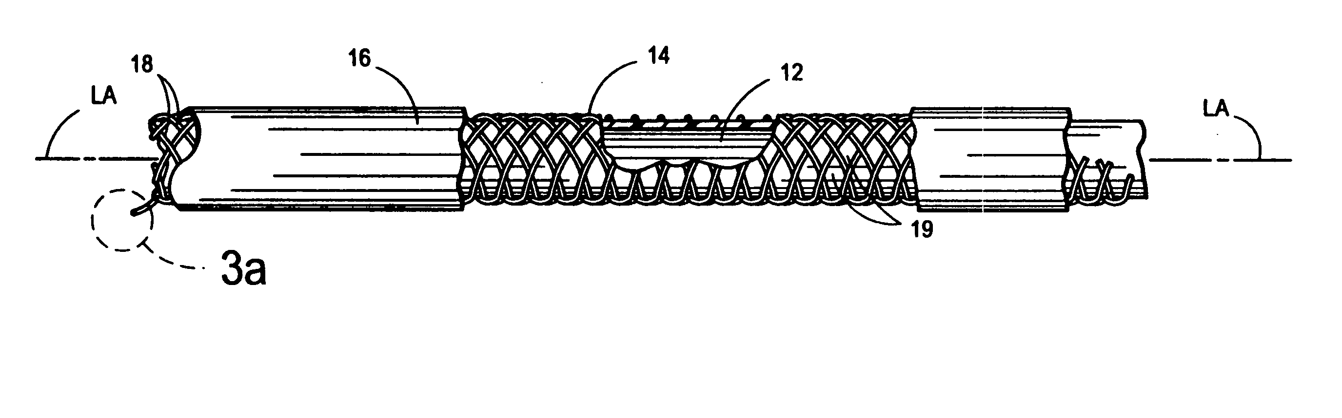
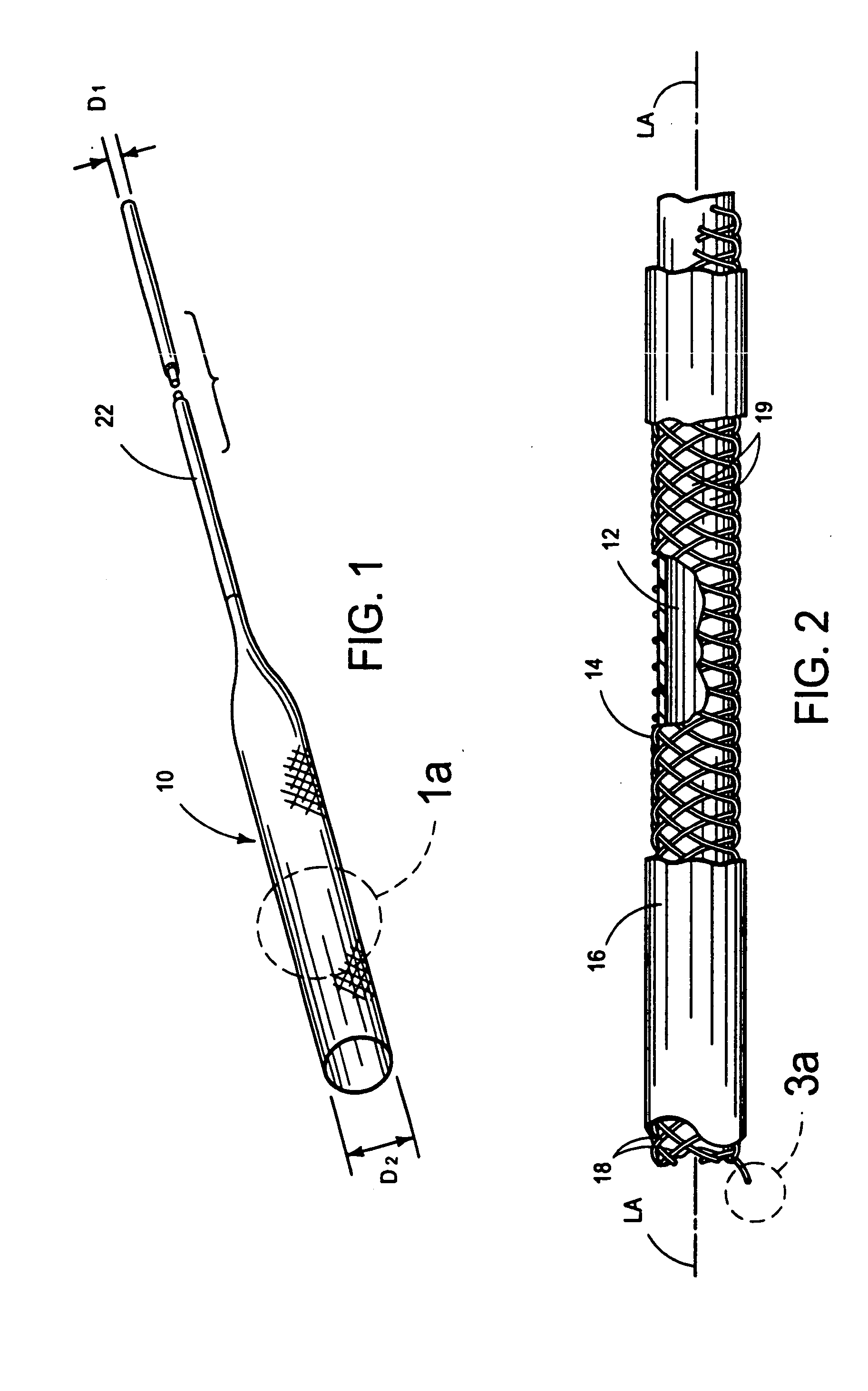
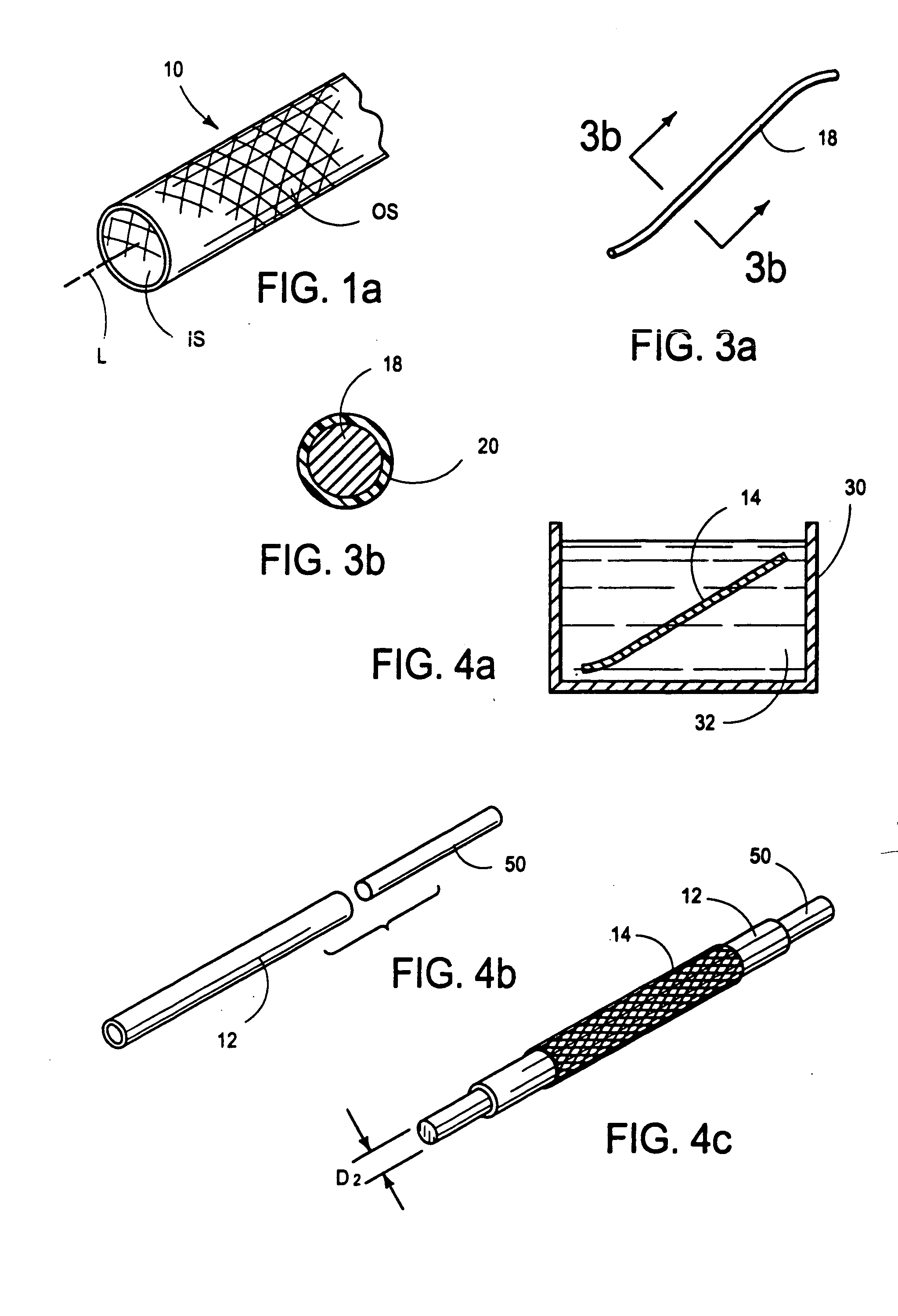
[0040] With reference to FIGS. 1-3b, there is shown an integrally stented tubular graft 10 of the present invention. The preferred integrally stented graft 10 comprises a tubular base graft 12, a PTFE-coated stent 14 and an outer layer of elastomer 16. Stent 14 is formed of metal, such as an alloy of cobalt, chromium, nickel or molybdenum, wherein the alloying residue is iron. One specific example of a commercially available alloy which may is usable to form the wires 18 of the stent 14 is Elgiloy (The Elgiloy Company, 1565 Fleetwood Drive, Elgin, Ill. 60120. Stent 14 may be radially compressed to a smaller diameter D1 and radial constraint, as may be applied by the s...


PUM

PropertyMeasurementUnit
Diameteraaaaaaaaaa
Biocompatibilityaaaaaaaaaa

Abstract

A polymer coated stent is disclosed. The stent may be a self-expanding stent or a balloon-expandable stent. The metal surface of the stent is coated with a polymer for enhanced biocompatibility. Amongst the various polymers that can comprise the coating of the stent are fluorine-containing polymers such as polytetrafluoroethylene (PTFE). Methods are also disclosed for depositing the coating on the surface of the stent.

Description

[0001] This is a continuation of U.S. patent application Ser. No. 10 / 001,765, filed on Oct. 31, 2001, which is a continuation in part of application Ser. No. 09 / 358,350 filed Jul. 21, 1999, now pending, which is a division of U.S. patent application Ser. No. 08 / 675,644, filed Jul. 3, 1996, now issued as U.S. Pat. No. 5,928,279.BACKGROUND ART [0002] The present invention pertains generally to medical devices and their methods of manufacture, and more particularly to tubular grafts having integral, radially expandable stents, for implantation in a cavities or passageways (e.g., ducts or blood vessels) of the body. A. Stents [0003] The prior art has included a number of radially expandable stents which may be initially deployed in a radially collapsed state suitable for transluminal insertion via a delivery catheter, and subsequently transitioned to a radially expanded state whereby the stent will contact and engage the surrounding wall or the anatomical duct or body cavity within whi...

Claims


Application Information

Patent Timeline
IPC IPC(8): A61F2/00A61F2/90A61L31/10A61L31/14B29C53/58
CPCA61F2/07A61F2/90A61F2240/001A61F2250/0067A61L31/10A61L31/14A61F2002/075B29K2027/18B29K2227/18B29L2031/7534B29C53/58A61F2/915C08L59/00
Inventor SHANNON, DONALD T.KUO, CHRISTU, BENNY
Owner SHANNON DONALD T
Why Eureka
Try Eureka