Catadioptric projection objective with geometric beam splitting

a catadioptric and beam splitting technology, applied in the field of catadioptric projection objectives, can solve the problems of increasing the difficulty of providing purely refractive systems with adequate color correction, unable to meet the requirements of color correction, and the production of polarization-selectively effective beam splitter layers is difficult, so as to achieve stable mounting of optical components, increase the image-side numerical aperture, and improve the effect of projection quality

Inactive Publication Date: 2005-06-02
CARL ZEISS SMT GMBH
View PDF25 Cites 711 Cited by
  • Summary
  • Abstract
  • Description
  • Claims
  • Application Information

AI Technical Summary

Benefits of technology

[0020] It is an object of the invention to provide catadioptric projection objectives which, with a finite working distance, permit a higher projection quality, even at extremely high numerical apertures. In this case, a beneficial geometry for stable mounting of optical components

Problems solved by technology

For the aforementioned short wavelengths, however, it becomes more and more difficult to provide purely refractive systems with adequate correction of color errors (chromatic aberration), since the Abbe constants of suitable transparent materials are relatively close to one another.
The disadvantage with such systems is that suitable transparent materials for the production of a beam splitter cube are available only to a limited extent in the required large volumes.
In addition, the production of the polarization-selectively effective beam splitter layers presents considerable difficulties.
An incomplete polarization-selective action can lead to the production of leakage transmission dependent on the angle of incidence and therefore to intensity inhomogeneities in the projection.
The complex folding geometries with a large number of optical components physically close to one another mean that considerable mechanical and mounting problems may be expected in the practi

Method used


Image

  • Catadioptric projection objective with geometric beam splitting
  • Catadioptric projection objective with geometric beam splitting
  • Catadioptric projection objective with geometric beam splitting

Examples


Embodiment Construction

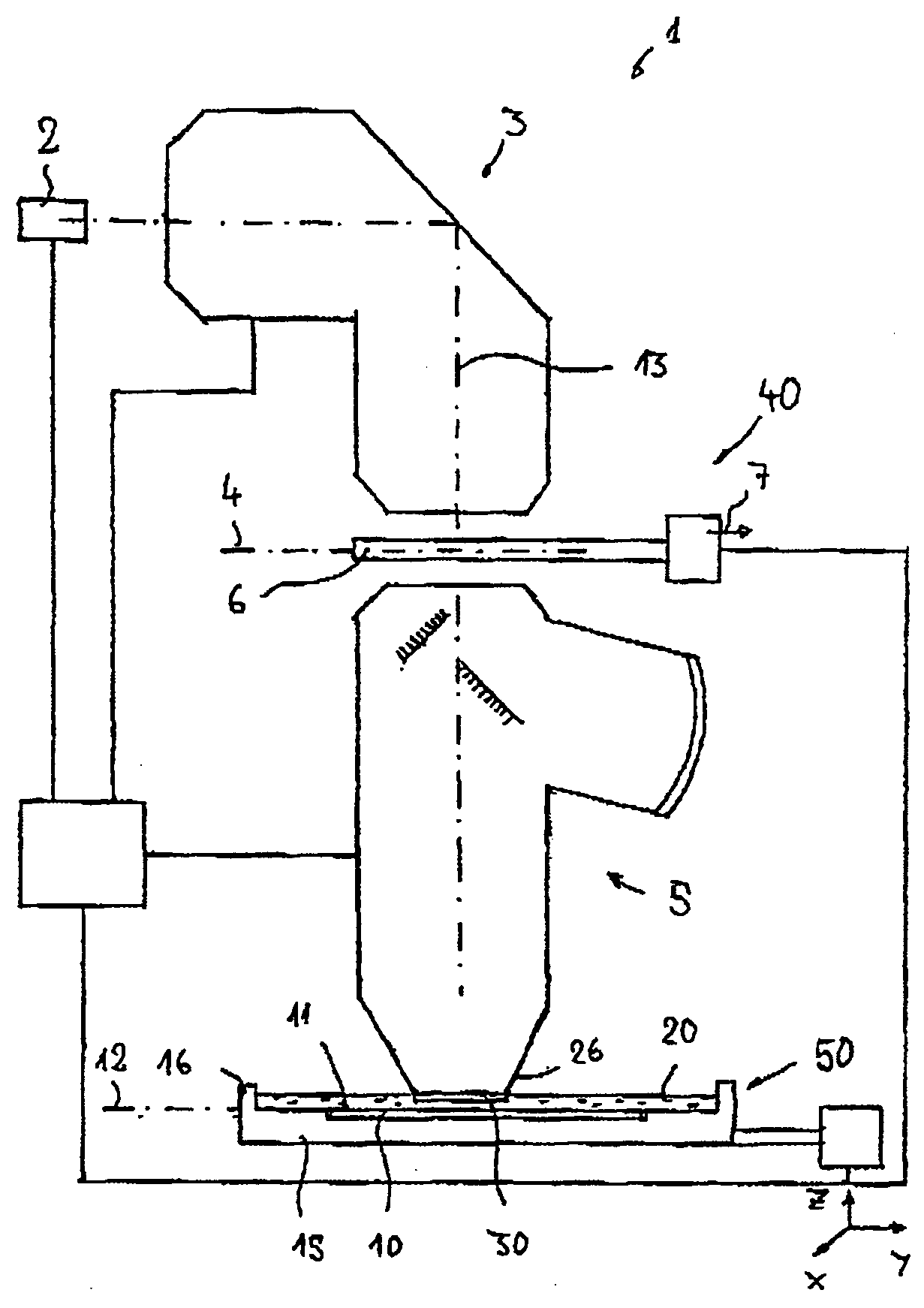
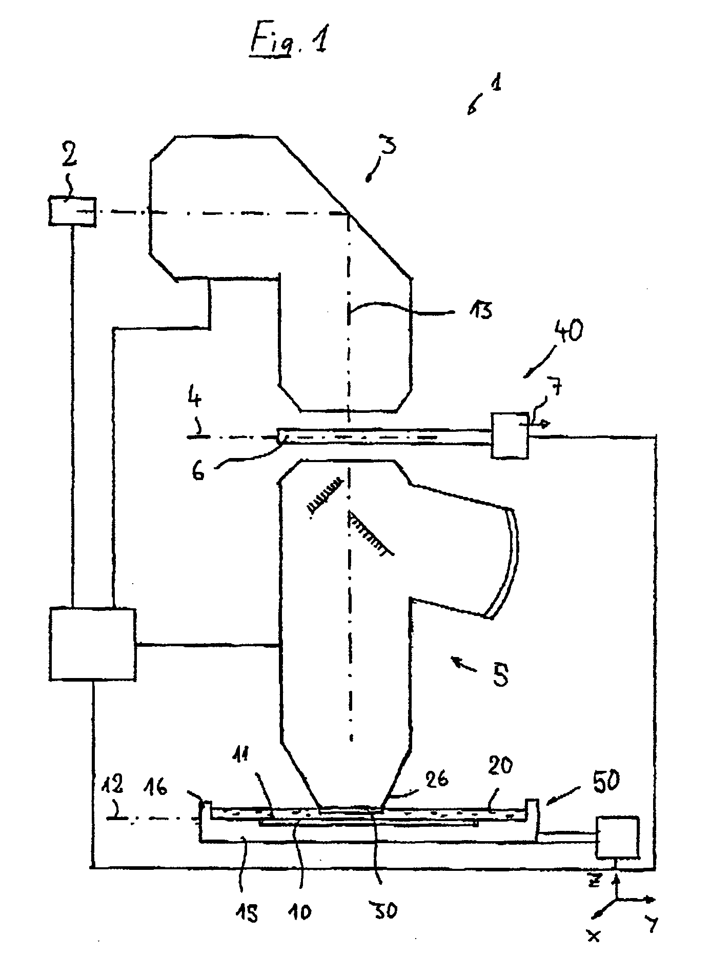
[0073] In the following description of preferred embodiments, the term “optical axis” designates a straight line or a series of straight line sections through the centers of curvature of the optical components. The optical axis is folded at folding mirrors (deflection mirrors) or other reflective surfaces. Directions and distances will be described as “image-side” if they are oriented in the direction of the image plane or of the substrate to be exposed and located there, and as “object-side” if they are oriented toward the object plane or a reticle located there with reference to the optical axis. In the examples, the object is a mask (reticle) having a pattern of an integrated circuit, it can also be another pattern, for example a grating. In the examples, the image is projected onto a wafer provided with a photoresist layer which acts as a substrate; other substrates, for example elements for liquid crystal displays or substrates for optical gratings, are also possible.

[0074] In...


PUM


Abstract

A catadioptric projection objective is used to project a pattern arranged in an object plane of the projection objective into an image plane of the projection objective with the formation of at least one real intermediate image and has an image-side numerical aperture NA>0.7. The projection objective comprises an optical axis and at least one catadioptric objective part that comprises a concave mirror and a first folding mirror. There are a first beam section running from the object plane to the concave mirror and a second beam section running from the concave mirror to the image plane. The first folding mirror is arranged with reference to the concave mirror in such a way that one of the beam sections is folded at the first folding mirror and the other beam section passes the first folding mirror without vignetting, the first beam section and the second beam section crossing one another in a cross-over region.

Description

[0001] This is a Continuation-in-Part Application of pending prior application Ser. No. 09 / 751,352, filed Dec. 27, 2000. The present Application additionally claims benefit of Provisional Application No. 60 / 511,673, filed Oct. 17, 2003BACKGROUND OF THE INVENTION [0002] 1. Field of the Invention [0003] The invention relates to a catadioptric projection objective for projecting a pattern arranged in an object plane of the projection objective into an image plane of the projection objective with the formation of at least one real intermediate image at an image-side numerical aperture NA>0.7. [0004] 2. Description of the Related Prior Art [0005] Projection objectives of this type are used in microlithography projection exposure systems for producing semiconductor components and other finely structured components. They are used to project patterns of photo masks or engraved plates, which in the following text will generally be designated masks or reticles, onto an object coated with a...

Claims


Application Information

Patent Timeline
IPC IPC(8): G02B13/14G02B13/18G02B17/08G03F7/20
CPCG02B13/143G02B13/18G02B13/22G02B17/08G02B17/0812G03F7/70966G03F7/70225G03F7/70241G03F7/70275G03F7/70341G03F7/70958G02B17/0892
Inventor SHAFER, DAVID R.EPPLE, ALEXANDERDODOC, AURELIANBEIERL, HELMUTULRICH, WILHELM
Owner CARL ZEISS SMT GMBH
Why Eureka
Try Eureka