
Method and apparatus for gas treatment using non-equilibrium plasma

a plasma and gas treatment technology, applied in the direction of physical/chemical process catalysts, metal/metal-oxide/metal-hydroxide catalysts, separation processes, etc., can solve the problems of low efficiency of decomposition treatment, and inapplicability, so as to improve the decomposition efficiency of treated gas and efficiently decompose

Inactive Publication Date: 2005-06-02
YAMAHA CORP
View PDF1 Cites 62 Cited by
  • Summary
  • Abstract
  • Description
  • Claims
  • Application Information

AI Technical Summary

Benefits of technology

[0017] It is an object of the invention to provide a method and an apparatus for gas treatment, which can be performed using non-equilibrium plasma caused by use of discharge electrodes with a relatively low cost.
[0018] The gas treatment method of this invention is characterized in that a plurality of photocatalyst members each including photocatalyst, solid substance (excluding photocatalyst), and another catalyst (excluding photocatalyst) are arranged in a non-equilibrium plasma region, into which a treated gas is introduced and is then subjected to decomposition. That is, the treated gas is directly decomposed by the non-equilibrium plasma and is also decomposed by the photocatalyst excited by the non-equilibrium plasma; thus, it is possible to improve the decomposition efficiency for the treated gas. Herein, the photocatalyst member is preferably formed in a solid shape, wherein the photocatalyst is solely used or is supported by another catalyst. The catalyst (excluding the photocatalyst) includes one element or two or more elements selected from among Ag, Au, Ce, Co, Cr, Cu, Fe, Li, Ni, Mn, Mo, Pd, Pt, Rh, V, W, and Zn. In addition, another catalyst includes 5 weight percentage of one element or two or more elements selected from among Ag, Au, Ce, Co, Cr, Cu, Fe, Li, Ni, Mn, Mo, Pd, Pt, Rh, V, W, and Zn, which are supported by a prescribed catalyst support whose specific surface area is 10 m2 / g or more.
[0019] Preferably, the photocatalyst is composed of titanium oxide, which can be reacted upon ultraviolet radiation or visible radiation. In addition, the solid substance is preferably made by one element or two or more elements selected from among the adsorbent porous substance, dielectric substance, clayey substance, and synthetic resin. Herein, the adsorbent porous substance has a specific surface area that is 200 m2 / g or more and is preferably made by one element or two or more elements selected from among HY zeolite, HX zeolite, H mordenite, silica alumina, and metal silicate. Alternatively, the adsorption porous substance has a specific surface area that ranges from 10 m2 / g to 750 m2 / g and is preferably made by one element or two or more elements selected from among silica alumina, zeolite, silica gel, zirconia, and titania. The non-equilibrium plasma is preferably caused by any one of pulse-streamer discharge, silent discharge, and surface discharge. By use of the aforementioned discharge, it is possible to suppress the amount of nitrogen oxide (NOx) and carbon monoxide (CO), which occur during decomposition of the treated gas.

Problems solved by technology

The gas treatment method using the thermal plasma may produce radicals, which are normally difficult to create, so as to actualize specific chemical reactions.
The conventional gas treatment methods have various problems due to low energy efficiencies, unwanted occurrence of intermediate products, and low efficiency of decomposition treatment.
In particular, the pulse-streamer discharge is relatively expensive and is not practical because it requires a high voltage pulse generator for generating pulses having sharp rises.
In order to improve the decomposition treatment efficiency, it is possible to provide various methods using a photocatalyst such as titanium dioxide and using an adsorbent such as alumina; however, no high-efficiency substance serving as both a photocatalyst and an adsorbent is provided conventionally.
The spot discharge (or packed-bed type discharge) using a photocatalyst such as titanium dioxide has problems due to incapability of suppressing the occurrence of nitrogen oxides (NOx).
Therefore, the aforementioned problems have not been solved yet.

Method used


Image

  • Method and apparatus for gas treatment using non-equilibrium plasma
  • Method and apparatus for gas treatment using non-equilibrium plasma
  • Method and apparatus for gas treatment using non-equilibrium plasma

Examples


first embodiment

1. First Embodiment

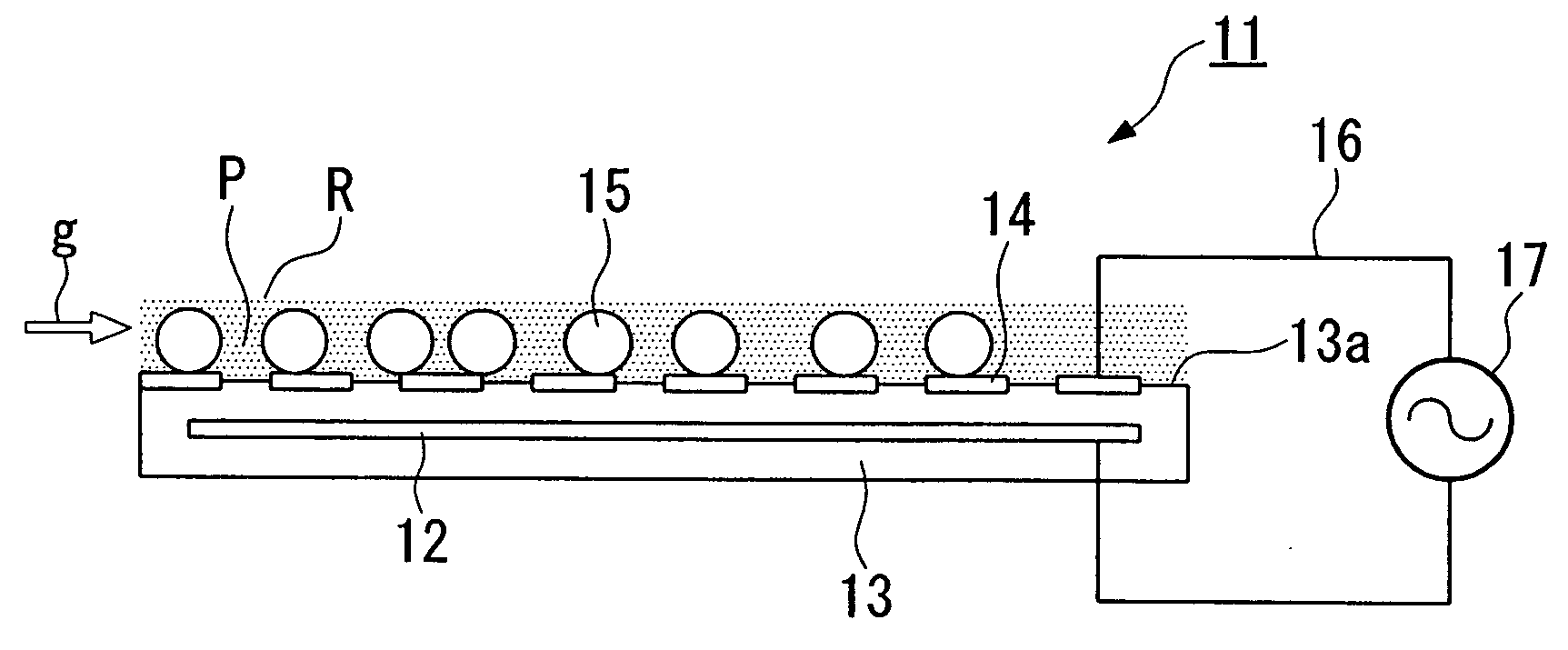
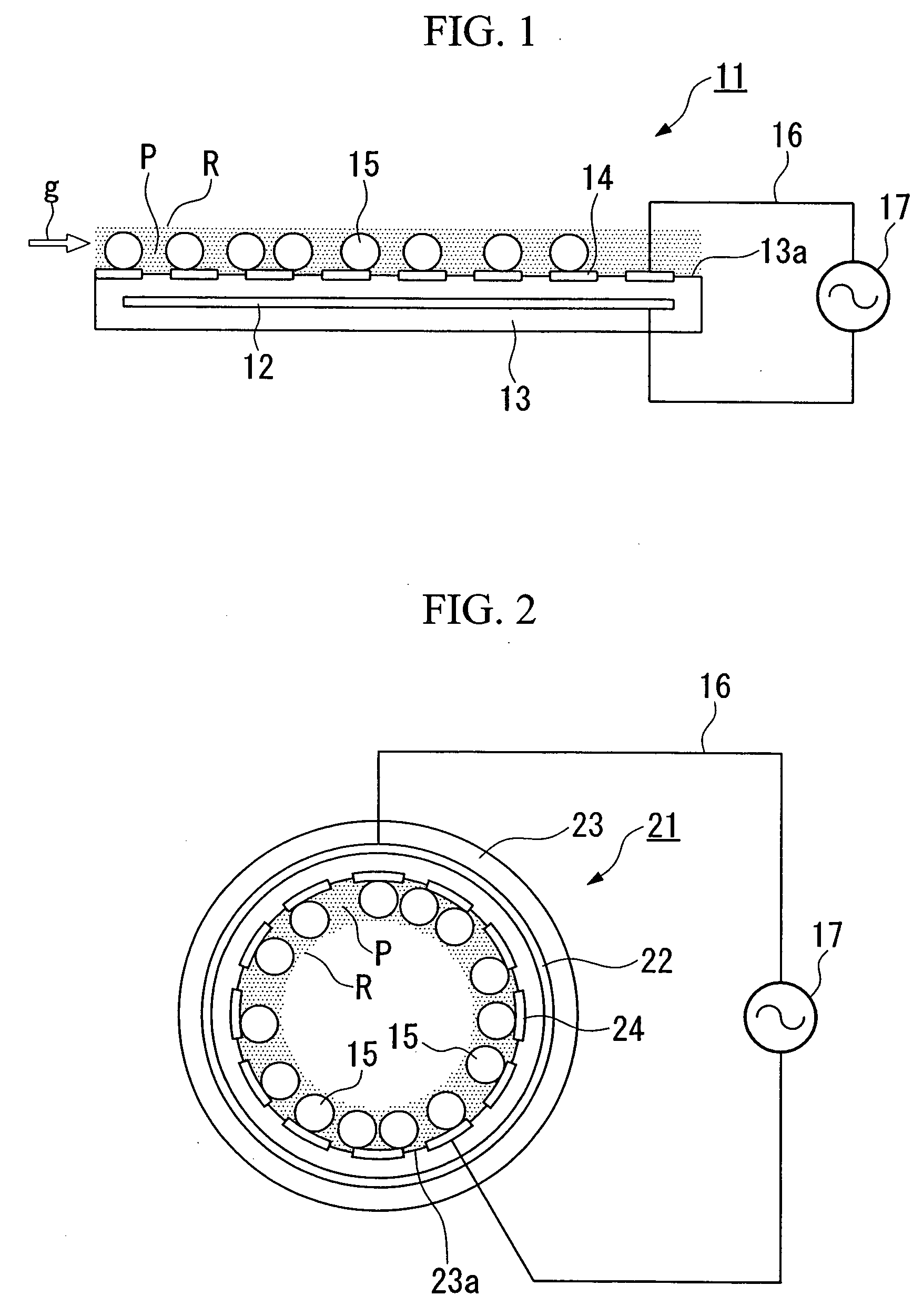
[0044]FIG. 1 diagrammatically shows the constitution of a surface discharge electrode for use in a gas treatment apparatus in accordance with a first embodiment of the invention.

[0045] A surface discharge electrode 11 shown in FIG. 1 is roughly formed as a planar plate electrode having a disk-like shape, wherein it comprises a ground electrode 12 having a thin disk shape, an insulator 13 having a thick disk shape encompassing the ground electrode 12, a plurality of spiral surface electrodes 14 formed on an upper surface (or a main surface) 13 a of the insulator 13, and a plurality of photocatalyst members 15 each containing photocatalyst and solid substance (excluding photocatalyst), which are arranged in a non-equilibrium plasma region R, wherein the ground electrode 12 and the surface electrode 14 are connected with a power source 17 via wires 16.

[0046] The aforementioned surface discharge electrode 11 is not necessarily limited in the outline shape and size t...

second embodiment

2. Second Embodiment

[0079]FIG. 2 diagrammatically shows the constitution of a surface discharge electrode for use in a gas treatment apparatus in accordance with a second embodiment of the invention, wherein parts identical to those of the first embodiment shown in FIG. 1 are designated by the same reference numerals.

[0080] A surface discharge electrode 21 comprises an ground electrode 22 having a pipe-like shape (or a cylindrical shape) composed of a conductive material, an insulator 23 having a pipe-like shape (or a cylindrical shape) composed of an insulating material, which encompasses the ground electrode 22 in a closed state, and a plurality of surface electrodes 24 each having a stripe shape that are arranged on an interior circumferential wall 23a of the insulator 23 in a coaxial manner with the ground electrode 22, as well as a photocatalyst member 15 (including photocatalyst and solid substance) arranged in a non-equilibrium plasma region R on the surface electrode 24. Al...

third embodiment

3. Third Embodiment

[0084]FIG. 4 is a cross sectional view showing essential parts of a gas treatment apparatus in accordance with a third embodiment of the invention, wherein parts identical to those of the first embodiment shown in FIG. 1 are designated by the same reference numerals.

[0085] A gas treatment apparatus 31 is installed in an exhaust pipe arranged in an incinerator for treatment of general waste and industrial waste, wherein a plurality of surface discharge electrodes 34 (FIG. 4 shows three sets of surface discharge electrodes 34 arranged in parallel with prescribed distances therebetween) are arranged in a non-equilibrium plasma region R actualized by a treated gas g inside of an exhaust pipe 35 in such a way that they block the exhaust flow in the exhaust pipe 35. The space between the adjacently arranged surface discharge electrodes 34 is filled with photocatalyst members 15 each including photocatalyst and solid substance. The surface discharge electrode 34 compris...


PUM

PropertyMeasurementUnit
specific surface areaaaaaaaaaaa

Abstract

A gas treatment method is actualized by arranging a plurality of photocatalyst members each including photocatalyst, solid substance, and catalyst in a region of non-equilibrium plasma, which is produced using a surface discharge electrode and into which a treated gas such as an exhaust gas and a harmful gas including harmful chemical substances is introduced and is then subjected to decomposition. The surface discharge electrode comprises a ground electrode, an insulator encompassing the ground electrode, and a plurality of surface electrodes that are arranged relative to the ground electrode via the insulator, by which the non-equilibrium plasma is produced upon electrification. A gas treatment apparatus is constituted by arranging a plurality of surface discharge electrodes, each having a plurality of through holes penetrating in a thickness direction, between which a plurality of photocatalyst members are arranged.

Description

BACKGROUND OF THE INVENTION [0001] 1. Field of the Invention [0002] This invention relates to methods and apparatuses for gas treatment using non-equilibrium plasma produced by use of surface discharge electrodes. [0003] This application claims priority on Japanese Patent Application No. 2003-364898, the content of which is incorporated herein by reference. [0004] 2. Description of the Related Art [0005] Exhaust gases emitted from incinerators for general wastes and industrial wastes include harmful chemical substances such as NOx, SOx, and dioxin. In order to avoid environmental pollution and undesirable effects on human bodies, it is required that harmful gases containing harmful chemical substances be rendered harmless by decomposition treatment and then be discharged to the atmosphere. [0006] Conventionally, various gas treatment methods are developed as decomposition treatment methods for harmful gases, among which a specific gas treatment method using electric discharge was de...

Claims


Application Information

Patent Timeline
Patent Type & Authority Applications(United States)
IPC IPC(8): B01D53/32B01D53/74B01D53/86B01J19/08B01J23/00F01N3/08F01N3/20H05H1/24
CPCB01D53/32B01D2255/802B01D2259/818Y02T10/26F01N3/2086H05H1/24F01N3/0892Y02T10/12H05H1/2425H05H1/2437H05H1/2443H05H1/2418H05H2245/15H05H1/2439
Inventor MUROI, KUNIMASAOGATA, ATSUSHI
Owner YAMAHA CORP
Learn More