
Electrical detectors for microanalysis

Inactive Publication Date: 2005-06-02
UNIV OF UTAH RES FOUND
View PDF15 Cites 177 Cited by
  • Summary
  • Abstract
  • Description
  • Claims
  • Application Information

AI Technical Summary

Benefits of technology

[0011] It would be an advance to provide a sensor capable of urging particles into single-file order for more direct (or close) contact between an interrogating electrode, or array of electrodes, and the particle(s) of interest. The development of microfabricated structures permitting detailed cellular characterization in solutions having ionic strengths similar to physiologic conditions would be a further advance to improve sensitivity and accuracy of dielectric characterization.
[0012] The present invention relates generally to detectors for analyzing microscale particles (0.01-100 microns in size) suspended in, or carried by, a fluid. Highly preferred embodiments of the invention find use in characterizing biological solutions and cells using microfabricated electric impedance-based sensors. Currently preferred embodiments of the invention accurately differentiate cells based on morphological, membrane, and / or cytoplasmic characteristics. Such embodiments can be leveraged for use in blood analysis to significantly and dramatically improve the current state of art in hematology analyzers. Microfabricated, EI-based sensors also have application in basic research markets, such as single cell electrophysiology. Certain embodiments of the invention operate as easy to use, inexpensive, disposable sensors for a variety of commercial products including, but not limited to, a micro-CBC analysis system for clinics, a gene therapy system for research and / or treatment of cancer and other disorders, and a research platform for cellular electrophysiology studies.
[0014] Devices within the ambit of the invention may be manufactured using lithographic micromachining techniques and equipment similar to solid-state component manufacturing equipment commercially established in the semiconductor industry. Such manufacturing capability permits a reduction in cost of components, for example, microelectro-mechanical chips used as a constituent component in cell detection sensors for hematology analyzers. Devices structured according to principles of the invention can be microfabricated into discrete, disposable, simple units capable of performing an equivalent level of hematology analysis to that of current state-of-the-art, large, costly units. Improvements inherent in certain embodiments of the invention provide a reduction in unit cost, pricing, and complexity of operation, while affording a simultaneous and equally significant increase in accessibility and mobility.
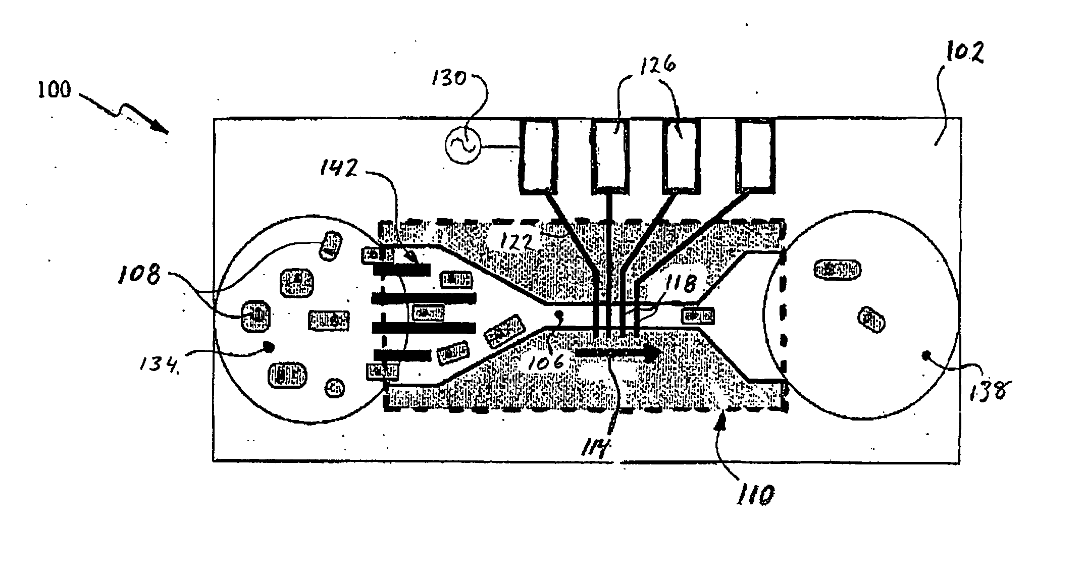
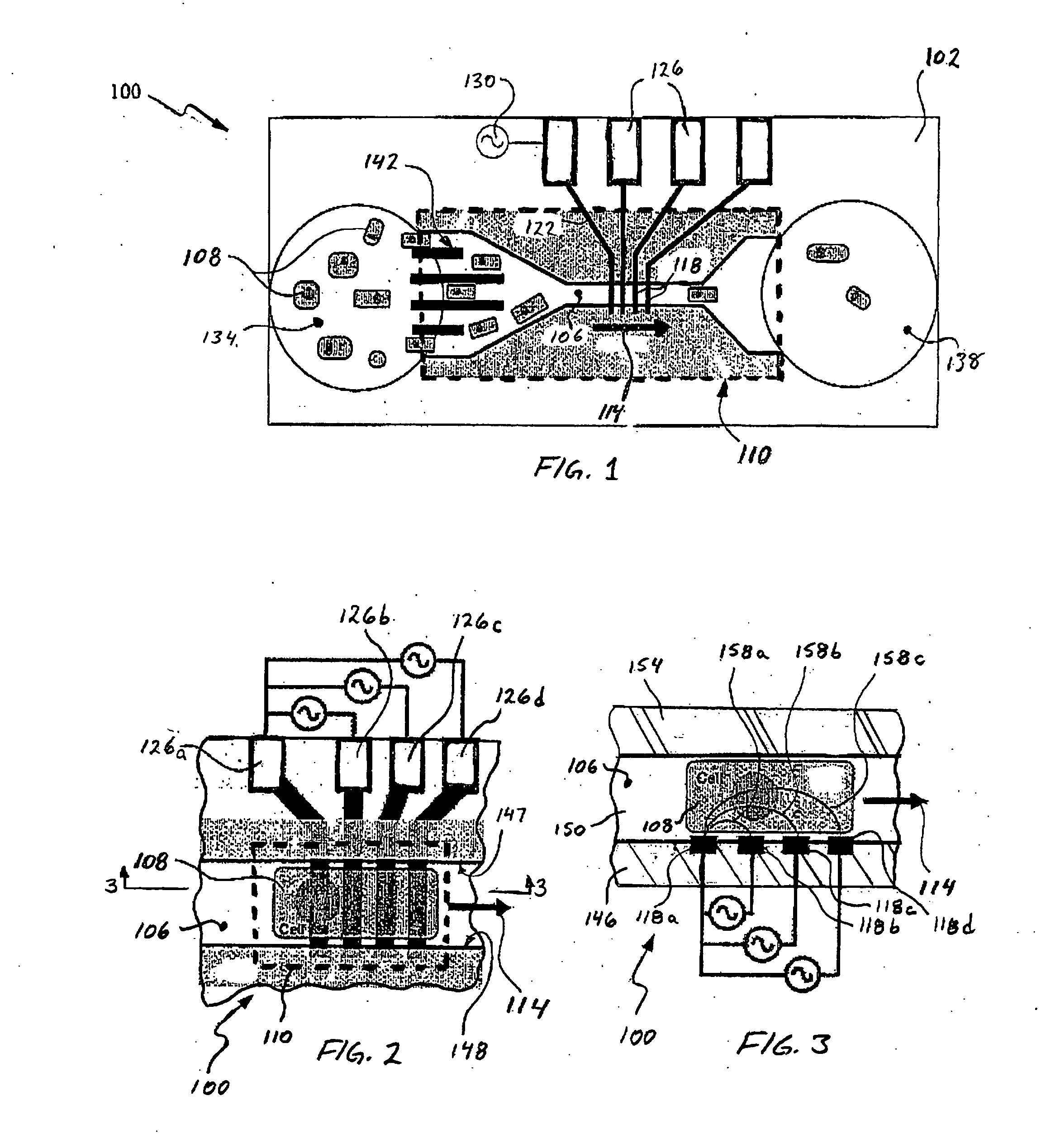
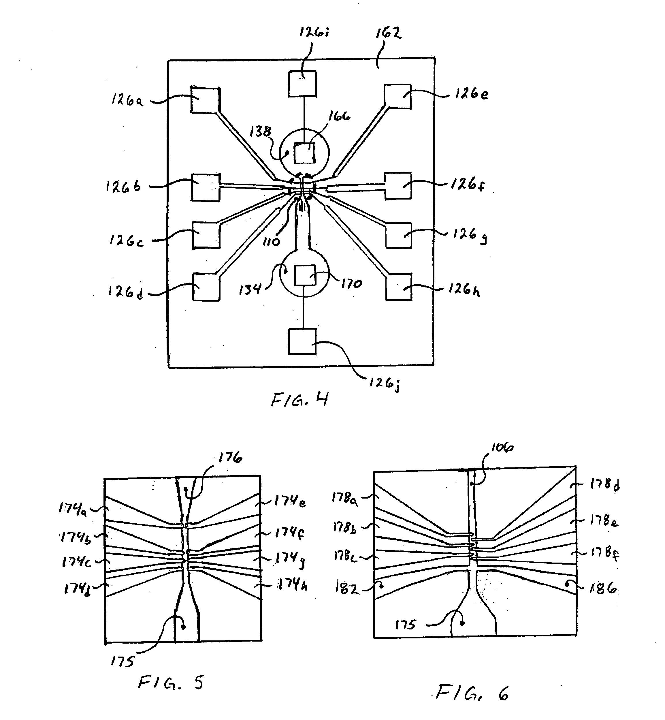
[0018] In certain currently preferred embodiments, a plurality of electrodes are disposed spaced apart along an axis of the microchannel to form an electrical signal therebetween oriented substantially along the channel's axis. Furthermore, most preferred embodiments include electrodes disposed only on one side of the microchannel, to reduce manufacturing cost and complexity. An interrogation zone occupies a portion of the microchannel having a cross-section of substantially uniform size along said length, and a plurality of the electrodes are disposed spaced apart in a direction oriented parallel to said length. Generally, an overall footprint of the MEMS device may be sized about 20 mm by about 20 mm as a trade-off between material cost, manufacturing yield, and ease of handling. In MEMS chips used to analyze blood cells, a cross-section of the microchannel may be sized between about 35 μm2 and about 250 μm2, or so. Devices having even smaller channels may be used for molecular or nanoparticle detection and interrogation. Certain embodiments include a filter disposed in association with an entrance to the microchannel and arranged to resist passage of clogging particles into the microchannel. It is convenient to form such a filter in the machinable layer.

Problems solved by technology

The subjective nature and relatively small total cell count of this technique were major limitations that significantly reduced the reliability of the manual CBC.
Due to the nature of current technology, state of the art hematology analyzers are expensive, physically large, complex units that demand highly skilled and trained technicians for operation.
Unfortunately, these state of the art macroscale electroporation techniques expose millions of cells to relatively poorly controlled electroporation pulses and therefore experience extremely poor injection ratios and cell survival ratios.
While this technique is suitable for research applications, it lacks the potential to be used effectively to electro-inject a larger number of cells.
Such technology suffers from an inherent spacing between the particles embedded in the sheath fluid and one or more interrogating sensors.
The sensor spacing inherent in devices incorporating a fluid sheath can reduce signal strength and cause an attendant loss in sensitivity and accuracy in collected data.

Method used


Image

  • Electrical detectors for microanalysis
  • Electrical detectors for microanalysis
  • Electrical detectors for microanalysis

Examples


Embodiment Construction

[0045] The following description provides specific details in order to provide a thorough understanding of the invention. The skilled artisan, however, would understand that the invention can be practiced without employing these specific details. Indeed, the invention can be practiced by modifying the illustrated devices and described methods and can be used in conjunction with certain apparatus and techniques already being conventionally used in industry. It is to be understood that reference to an item being “on” a layer, or carried by a substrate, is intended to encompass the structure as recited and also including one or more intervening layers. Furthermore, structure may be regarded as being carried “by” or being “on” a layer if the structure in question is formed “in” the referenced layer. With respect to material characterization, the word “machinable” is intended to encompass material in which patterns, or structural shapes, can be formed or manipulated using material remova...


PUM

PropertyMeasurementUnit
Lengthaaaaaaaaaa
Areaaaaaaaaaaa
Lengthaaaaaaaaaa

Abstract

Apparatus and methods for performing microanalysis of particles using a microelectrical-mechanical system (MEMS) chip to electrically interrogate the particles. The MEMS chip is typically manufactured using known lithographic micromachining techniques, employed for example, in the semiconductor industry. A substrate carries a plurality of microelectrodes disposed in a detection zone and spaced apart along an axis of a microchannel. The microchannel is sized in cross-section to cause particles carried by a fluid to move past the electrodes in single file. Impedance is measured between one or more pairs of electrodes to determine the presence of a particle in the detection zone. In certain embodiments used in cell manipulation, an electroporation signal may be applied between one or more pairs of electrodes to enhance permeability of a cell membrane. A structural arrangement may be provided to introduce a treatment substance into the microchannel in the vicinity of a cell, which may be restrained for a period of time in a treatment zone.

Description

CROSS-REFERENCE TO RELATED APPLICATION [0001] This application claims the benefit of the filing date of U.S. Provisional Patent Application Ser. No. 60 / 518,094, filed Nov. 7, 2003, for “Electrical Detectors for Microanalysis,” the contents of which are incorporated herein by reference.TECHNICAL FIELD [0002] The invention generally relates to detectors for microanalysis of particles carried in a fluid, and methods for making and using such detectors. In one preferred embodiment, the invention relates to detectors for characterizing whole blood based on the electric impedance of the whole blood components and cytometric phenotypes, as well as methods for making and using such detectors. BACKGROUND [0003] Electric impedance (EI) is the measure of the degree to which an electric circuit resists electric-current flow when a voltage is applied across its terminals. Impedance, expressed in Ohms, is the ratio of the applied voltage to current. In alternating current (AC) circuits, impedance...

Claims


Application Information

Patent Timeline
IPC IPC(8): B01L3/00C12M1/34C12Q1/68G01N15/12H01L29/08H01L35/24
CPCB01L3/502761B01L2200/0668B01L2300/0645C12M35/02G01N15/1056G01N15/1218G01N2015/1254B01L2300/0816G01N15/1031G01N15/1023G01N15/13G01N2015/135
Inventor RABBITT, RICHARD D.AYLIFFE, H. EDWARD
Owner UNIV OF UTAH RES FOUND
Learn More