
Method for reducing the adhesive properties of MEMS and anti-adhesion-coated device

a technology of anti-adhesion coating and mems, which is applied in the direction of soldering apparatus, instruments, photomechanical apparatus, etc., can solve the problems that the application of the anti-sticking layer from the liquid phase onto the mems structure is only possible with difficulty, and achieve the effect of preventing the adhesion of the micromechanical structur

Inactive Publication Date: 2005-06-02
ROBERT BOSCH GMBH
View PDF5 Cites 33 Cited by
  • Summary
  • Abstract
  • Description
  • Claims
  • Application Information

AI Technical Summary

Benefits of technology

[0010] In accordance with the present invention, the anti-stiction media are not applied directly to the functional wafer or MEMS wafer, but are applied, in the first process step, to a cap wafer. In subsequent process steps, this “seeded” cap wafer is durably bonded to the functional sensor wafer, i.e. the MEMS wafer. During this procedure, or later, the anti-stiction medium is evaporated, and deposited at least on parts of the surfaces of the MEMS wafer. Thereby the adhesion of the movable elements is prevented. However, in this context, no separate coating step is required for the MEMS wafer.
[0011] The method according to the present invention has the advantage of being able to be carried out particularly cost-effectively, and also of having the capability of being used to coat whole batches of wafers (of having batch capability). A further advantage is that one may use production equipment that is already in existence. This method is able to minimize or prevent contamination risks to other products (cross contamination) by anti-stiction media. The device according to the present invention is able to be produced in a particularly cost-effective manner.
[0013] Furthermore, it is of advantage that the cap wafer is bonded to the MEMS wafer with the aid of a sealing glass paste. The sealing glass paste closes off the cavity, the cap wafer and the MEMS wafer hermetically in a limiting way from the environment, and holds the evaporated anti-stick active agent on the inside of the cavity, where it at least partially coats adjacent surfaces.
[0016] Another example embodiment of the method according to the present invention provides doping the atmosphere within the closed chamber, especially of the oven, with the active agent, by impregnating a porous element, e.g., one consisting of silicone rubber or phenylsilicone rubber with the active agent, and accommodating the saturated element at a location in the chamber that is at a temperature of 200 to 300° C., e.g., in the supply tube of a gas flushing system. The oven flush gas takes up the active agent and introduces it into the closed chamber. One additional example embodiment provides doping the atmosphere inside the closed chamber with the active agent, by accommodating within the chamber an evaporator source made up of a storage vessel filled with the active agent. It is likewise advantageous to dope the atmosphere within the closed chamber with the active agent, in that the flush gas introduced into the chamber is first doped with the active agent, and especially in that the flush gas is displaced from the evaporator together with the active agent, or in that the flush gas bubbles through the active agent in a bubble vessel. In addition, it is advantageous to dope the atmosphere within the closed chamber with the active agent by evaporating the active agent from a storage flask through a valve via a heated supply line, and introducing it into the closed chamber.
[0018] For the coating method according to the present invention, an active agent from the compound class of the silanes may be used. Active agents from this compound class are well suited for the coating, and have particularly good anti-stick properties.
[0021] This prevents the adhesion of the micromechanical structures of the functional part among themselves, to the substrate and to the cap. It is possible to use particularly flat caps which extend over the micromechanical structure at a low height. Thereby, in turn, smaller designs of the microelectromechanical components are made possible.

Problems solved by technology

The application of the anti-sticking layer from the liquid phase onto the MEMS structures is possible only with difficulty, since capillary forces bond the MEMS during drying.

Method used


Image

  • Method for reducing the adhesive properties of MEMS and anti-adhesion-coated device
  • Method for reducing the adhesive properties of MEMS and anti-adhesion-coated device
  • Method for reducing the adhesive properties of MEMS and anti-adhesion-coated device

Examples


Embodiment Construction

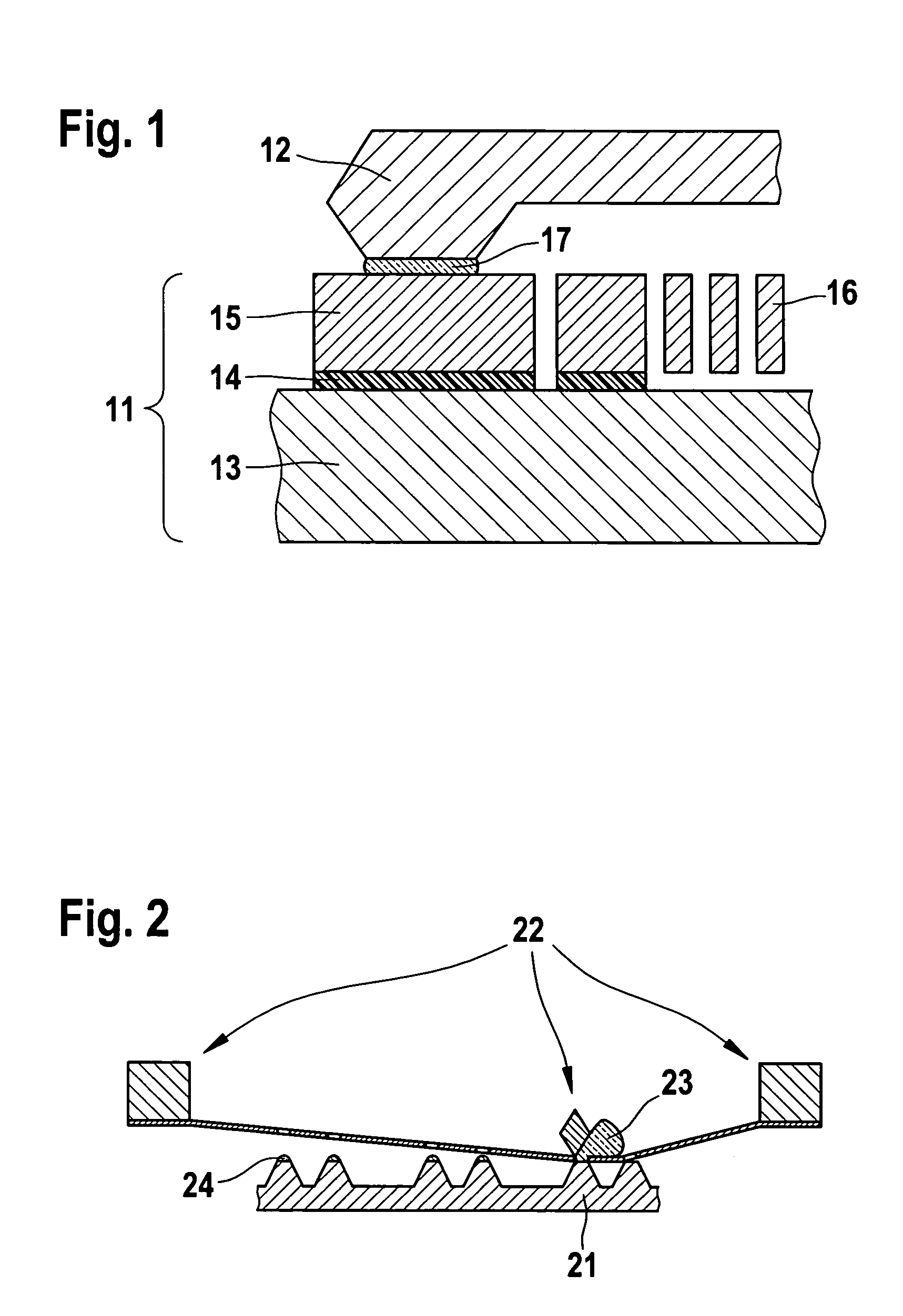
[0032]FIG. 1 shows an MEMS component 11 having a cap 12. MEMS component 11 is made up of a first layer or substrate 13, an insulating layer or sacrificial layer 14 and a second layer of functional layer 15 having patterned-out micromechanical elements 16. MEMS component 11 and cap 12 are bonded by a sealing glass 17.

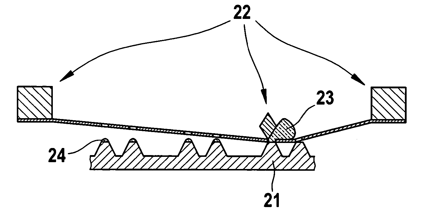
[0033]FIG. 2 shows the method of silk-screening sealing glass 23 onto a cap wafer 21. In one embodiment of the present invention, sealing glass 23 is applied to the edges of a cap wafer 21 with the aid of a silk-screeing system 22. The suitable layer thickness of sealing glass coating 24 applied, of, typically, 5 to 40 μm, is achieved by having one or several printing processes. According to one embodiment of the method according to the present invention, sealing glass 23 contains the anti-stick active agent.

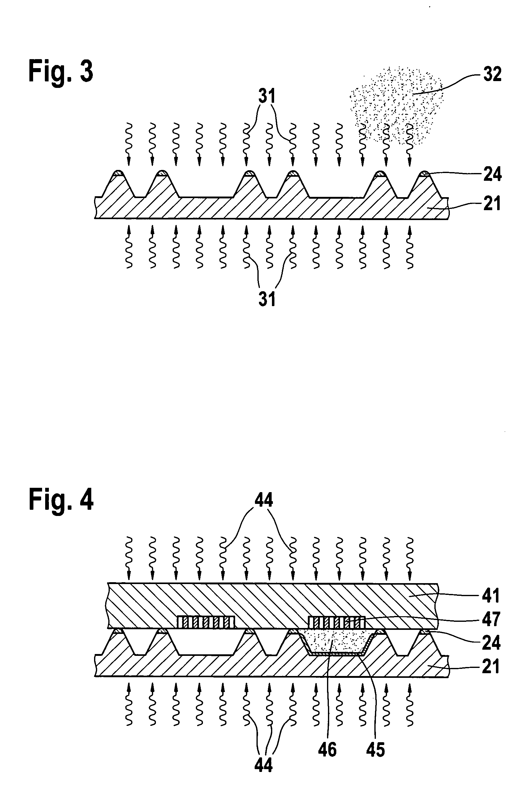
[0034]FIG. 3 shows the pre-bake process of a cap wafer 21 provided with sealing glass coating 24. In this context, the organic components of the sealing glass past...


PUM

PropertyMeasurementUnit
Temperatureaaaaaaaaaa
Pressureaaaaaaaaaa

Abstract

A method provides coating of the surface of a microelectromechanical structure (MEMS) wafer by using an anti-stick layer. The anti-stick material is initially applied to a cap wafer, and in subsequent steps this seeded cap wafer is bonded to the MEMS wafer. The anti-stick material is evaporated and deposited at least on parts of the surfaces of the MEMS wafer.

Description

FIELD OF THE INVENTION [0001] The present invention relates to microelectromechanical structures and a method for producing a coating layer on such structures. BACKGROUND INFORMATION [0002] Movable elements in microelectromechanical structures (MEMS) are able to stick to the fixed structures. As mechanisms for sticking together, among other things, mechanical overload, electrostatic discharge and chemical bonds come into consideration. In the chemical bonds, van der Waals interactions, ionic interactions, covalent bonds or metallic bonds may be determinative. Touching surfaces having high surface energy, such as silicon surfaces having a cover layer of OH groups or having a water film, may demonstrate strong binding forces which are then based on ionic interactions or covalent bonding (after removal of the water) and which hold the two surfaces together. [0003] The sticking described above may be prevented by coating the surfaces, using anti-adhesive layers, so called anti-sticking ...

Claims


Application Information

Patent Timeline
IPC IPC(8): B81B3/00B81C1/00H01L21/00H01L27/14B81C3/00H01L29/82H01L29/84
CPCB81C1/0096B81B3/0005
Inventor HENNING, FRANKMUELLER, LUTZHOEFER, HOLGERKAELBERER, ARND
Owner ROBERT BOSCH GMBH
Learn More