
Vacuum deposition device and pretreatment method for vacuum deposition

a vacuum deposition and vacuum deposition technology, applied in the direction of instruments, nuclear engineering, conversion screens, etc., can solve the problems of short distance that the film forming material can reach from the evaporator, easy peeling of the deposited layer, and large deterioration

Inactive Publication Date: 2005-06-09
FUJIFILM CORP +1
View PDF10 Cites 13 Cited by
  • Summary
  • Abstract
  • Description
  • Claims
  • Application Information

AI Technical Summary

Benefits of technology

[0012] It is an object of the present invention, which has been made in view of the above situation, to provide a vapor deposition device capable of forming an excellent deposition layer and a pretreatment method of carrying out such vacuum deposition.
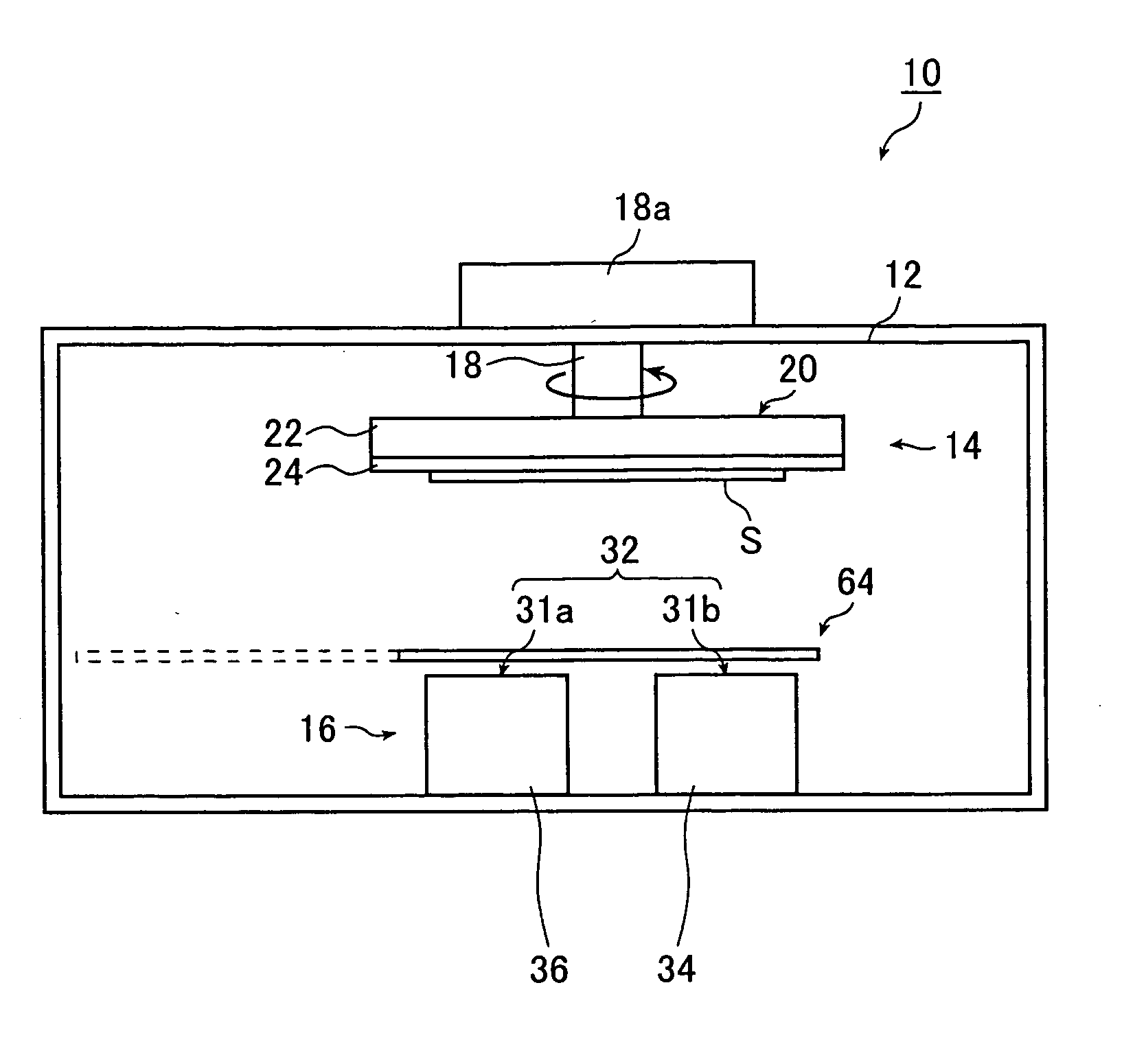
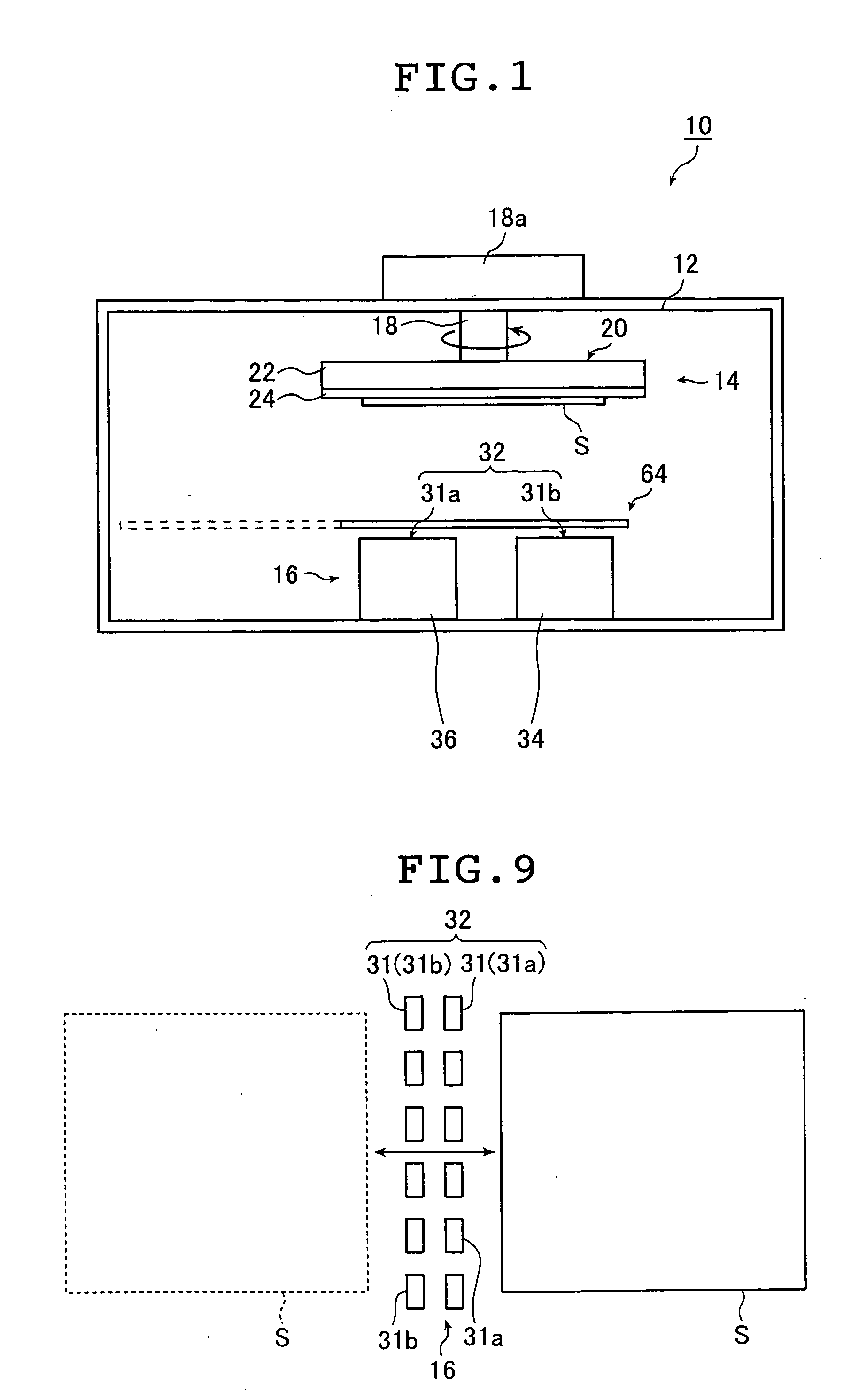
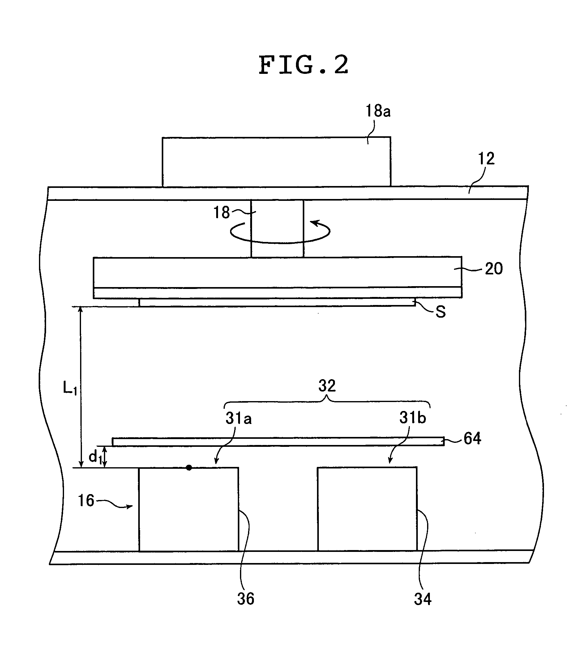
[0026] In order to attain the object described above, the invention also provides a pretreatment method for vacuum deposition comprising the step of preparing prevention means for preventing evaporated particles of one or more film forming materials from adhering to a substrate on which the one or more film forming materials are deposited in a vacuum deposition chamber, and melting the one or more film forming materials by heating in the vacuum deposition chamber at a pressure of 0.05 to 10 Pa while preventing the evaporated particles from adhering to the substrate for the vacuum deposition by using the prevention means.

Problems solved by technology

As a result, the distance that the film forming material evaporated from the evaporator can reach is short.
In addition, the adhesive strength of the deposited layer to the surface of the substrate lowers with the result that the deposited layer easily peels off and greatly deteriorates.

Method used


Image

  • Vacuum deposition device and pretreatment method for vacuum deposition
  • Vacuum deposition device and pretreatment method for vacuum deposition
  • Vacuum deposition device and pretreatment method for vacuum deposition

Examples


examples

[0161] One-source vacuum deposition, that is, one evaporator 31 in the evaporating unit 32 was used as shown in FIG. 3A, the evaporation conditions of the film forming materials were fixed, and the size and position of the shutter 64 were changed to compare the formed phosphor films in terms of adhesive strength and image characteristics (degree of structure).

Evaporator:

[0162] Cesium bromide (CsBr) powder having a purity of 4N or more and europium bromide (EuBr2) powder having a purity of 3N or more were prepared in an evaporator. When the trace elements in each powder were analyzed by means of ICP-MS (inductively coupled plasma spectrometry-mass spectrometry), the amounts of alkali metals (Li, Na, K, Rb) other than Cs in CsBr were each 10 ppm or less and the amounts of other elements such as alkali earth metals (Mg, Ca, Sr, Ba) were 2 ppm or less. The amounts of rare earth elements other than Eu in EuBrx were each 20 ppm or less and the amounts of other elements were each 10 ppm...


PUM

PropertyMeasurementUnit
Pressureaaaaaaaaaa
Distanceaaaaaaaaaa
Lengthaaaaaaaaaa

Abstract

The vacuum deposition device includes a vacuum deposition chamber, a vacuum evacuator for evacuating an inside of the chamber, an evaporating unit for evaporating one or more film forming materials in the chamber, a holding unit provided above the evaporating unit for holding a substrate for the vacuum deposition, and a preventing unit for preventing evaporated particles of the one or more materials from adhering to the substrate when the vacuum deposition is carried out at a pressure of 0.05 to 10 Pa. The pretreatment method for the vacuum deposition prepares the prevention unit in the chamber and melts the one or more materials by heating in the chamber at the pressure of 0.05 to 10 Pa while preventing the evaporated particles from adhering to the substrate by using the preventing unit.

Description

BACKGROUND OF THE INVENTION [0001] The present invention relates to a vacuum deposition device and a pretreatment for vacuum deposition and, more specifically, to a vacuum deposition device by which a high-quality film is deposited even when deposition is carried out under medium vacuum and a pretreatment method for such vacuum deposition. [0002] There are known a class of phosphors which accumulate a portion of applied radiations (e.g., X-rays, α-rays, β-rays, γ-rays, electron beam, and ultraviolet radiation) and which, upon stimulation by exciting light such as visible light, give off a burst of light emission in proportion to the accumulated energy. Such phosphors called “stimulable phosphors” are employed in medical and various other applications. [0003] Known as an exemplary application is a radiation image information recording and reproducing system which employs a sheet (phosphor sheet) having a layer (to be referred to as “phosphor film” hereinafter) containing this stimula...

Claims


Application Information

Patent Timeline
IPC IPC(8): C09K11/08G21K4/00C09K11/77C23C14/06C23C14/24C23C14/50C23C16/00
CPCC09K11/7733C23C14/0694G21K4/00C23C14/505C23C14/24Y02P20/141
Inventor ISODA, YUJIUCHIDA, KOHJI
Owner FUJIFILM CORP
Learn More