Fluid damper having continuously variable damping response

a technology of damper and fluid, which is applied in the direction of shock absorber, spring/damper, vibration suppression adjustment, etc., can solve the problems of fluids that may require special handling and disposal at the end of the useful service life of the vehicle, and the difficulty of packaging the piston with an appropriate coil, etc., to achieve the effect of reducing the manufacturing cost and reducing the volume of mr fluid

Active Publication Date: 2005-06-09
GM GLOBAL TECH OPERATIONS LLC
View PDF12 Cites 155 Cited by
  • Summary
  • Abstract
  • Description
  • Claims
  • Application Information

AI Technical Summary

Benefits of technology

[0011] Application of the variable electromagnetic field to the fluid produces changes in the viscosity of the fluid that in turn provides variable resistance to rotation of the hub and variable resistance to translation of the translatable member, thereby providing a damping apparatus having a continuously variable damping response.
[0012] One advantage of this invention compared with existing MR fluid based dampers, such as piston-based MR dampers, is believed to be lower manufacturing cost due to a reduced volume of MR fluid. A second advantage is believed to be that the apparatus of the present invention requires a smaller packaging envelope as compared to prior piston-based MR fluid dampers related to both the reduced volume of MR fluid required for its operation and the elimination of the need for a gas reservoir to accommodate fluid displacement as the damper is actuated. A third advantage is believed to be a reduction in the surface area of components in the damper mechanism that require anti-wear coatings due to the abrasive nature of the MR fluids. A fourth advantage is believed to be the ability to utilize relatively lower pressure and hence lower cost seals to seal the MR fluid due to the lower fluid operating pressures utilized in the present invention. A fifth advantage is believed to be the ability of the present invention to improve the linearity of the force-velocity characteristics of the actuator due to the absence of second order entry and exit effects of MR fluid flow found in prior art piston-based monotube devices. A final advantage is believed to be that the present invention may provide higher turn-up ratios in smaller packages as compared to prior piston-based MR fluid dampers.

Problems solved by technology

However, earlier problems with sedimentation and abrasion discouraged their use.
While MR fluid dampers of the types generally described above have been successfully used in CV-RTD applications and have demonstrated the ability to provide fast and continuous variable control of damping forces, they require that the hollow tube be substantially filled with MR fluid which is a relatively expensive material.
Furthermore, the fluids may require special handling and disposal at the end of the useful service life of the vehicle.
Also, the packaging of the piston with an appropriate coil can be difficult when high turn-up ratios at high velocities are desired due to the relatively large size of the coil required to provide these ratios.

Method used


Image

  • Fluid damper having continuously variable damping response
  • Fluid damper having continuously variable damping response
  • Fluid damper having continuously variable damping response

Examples


first embodiment

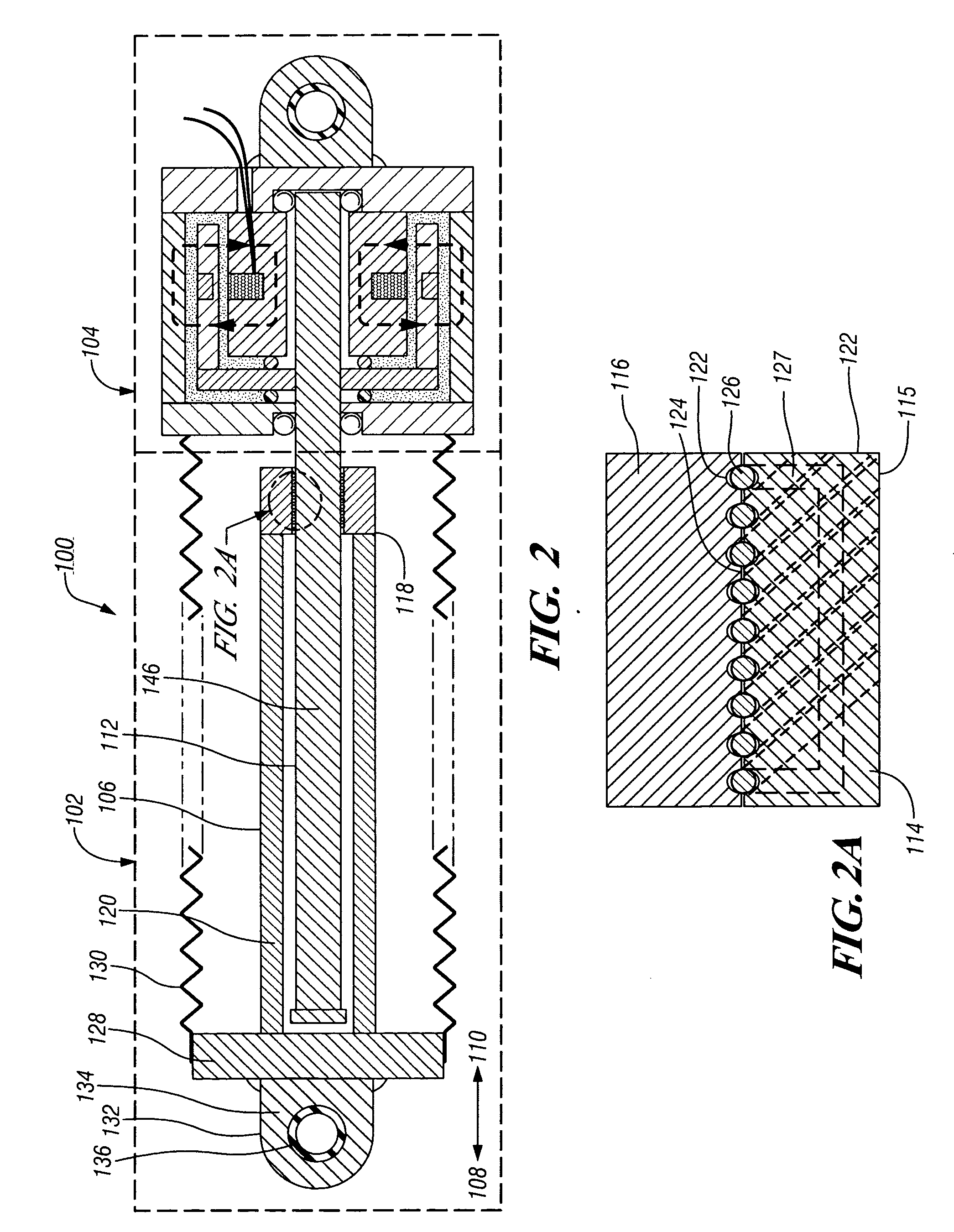
[0032] Referring to FIGS. 2-3, damping mechanism 104 is illustrated wherein hub 154 generally has the shape of a cylindrical cup that is fixed to shaft 114. In this embodiment, channel 176 has the shape of a pair of concentric cylindrical cups of different diameter which are joined by a lateral section at their rims. Channel 176 is defined and bounded generally by a portion of inner surface 170 of sidewall 168, inner surface 165 of first end 164 and outer surface 174 of hub 154; inner surface 182 of hub 154 and outer surface 184 of cylindrical core 186; and inner surface 173 of second end 172. Hub 154 preferably comprises cylindrical base 188 that is fixed to shaft 114 using known joining methods, such as an interference fit, welding, brazing, staking or other methods, and cylindrical wall 190 which extends outwardly from cylindrical base 188. Cylindrical base 188 preferably comprises a non-magnetic material, such as austenitic steel, aluminum or other non-magnetic material. Cylindr...

second embodiment

[0034] Referring to FIG. 4, damping mechanism 104 is illustrated, wherein hub 154 generally has the shape, features and construction of cylindrical cup-shaped hub 154 described above with regard to FIGS. 2-3. Outer surface 174 of hub 154 is located proximate inner surface 170 of sidewall 168 and inner surface 165 of first end 164 in spaced adjacency, such that channel 176 is formed thereby. Channel 176 is further defined by a pair of seals 198 that are located between inner surface 165 of first end 164 and outer surface 174 of hub 154 in order to retain fluid 160 within channel 176. Fluid 160 is preferably an MR fluid. When an MR fluid 160 is used, damping mechanism 104 also comprises coil 200 which in turn comprises a plurality of wire windings and may also incorporate a magnetic core in order to enhance the strength of magnetic fields 158 that may be produced by coil 200. Coil 200 may be attached and operated as described above with regard to the apparatus of FIGS. 2-3. Damping me...

third embodiment

[0035] Referring to FIG. 5, damping mechanism 104 is illustrated, wherein hub 154 generally has the shape of a cylindrical disk that is fixed to shaft 114. In this embodiment, channel 176 also generally has the shape of a cylinder which is defined generally by outer surface 174 of hub 154 and a cylindrical portion of inner surface 170 of sidewall 168. Hub 154 preferably comprises a cylindrical disk that is fixed to shaft 114 using methods such as those described above with regard to FIGS. 2-3. Hub 154 comprises a magnetic material, such as magnetic steel. Outer surface 174 of hub 154 is located proximate a cylindrical portion of inner surface 170 of sidewall 168 in spaced adjacency, such that channel 176 is formed thereby. Channel 176 is further defined by a pair of seals 198 that are located between inner surface 170 of sidewall 168 and outer surface 174 of hub 154 in order to retain fluid 160 within channel. When an MR fluid 160 is used, damping mechanism 104 also comprises coil 2...


PUM


Abstract

An improved damping apparatus that utilizes a fluid having a viscosity that may be varied by the application of an electromagnetic field, such as a magnetorheological fluid or an electrorheological fluid, to provide the damping response. The damping apparatus includes a linear to rotary conversion mechanism which comprises a translatable member that is adapted for linear translation in a forward and a reverse direction and a rotatable member comprising a rotatable shaft that is rotatably coupled to the translatable member; wherein translation of the translatable member in one of the forward or the reverse directions produces a forward or a reverse rotation of the rotatable member and shaft, respectively. The damping apparatus also includes a damping mechanism which comprises a hub that is fixed to the shaft, a means for generating a variable electromagnetic field in response to an applied electrical signal that may be continuously varied in response to an input signal that is representative of a desired damping force and a fluid having a viscosity that may be continuously varied by application of the electromagnetic field that is in touching contact with the hub. Application of the variable electromagnetic field to the fluid produces changes in the viscosity of the fluid that in turn provides variable resistance to rotation of the hub and resistance to translation of the translatable member, thereby providing a damping apparatus with a continuously variable damping response.

Description

TECHNICAL FIELD [0001] The present invention relates generally to damping devices used in controlled damping applications, such as semi-active vehicle suspension systems. More particularly, the present invention relates to high performance, continuously variable, real time damping devices using magnetorheological (MR) or electrorheological (ER) fluids. BACKGROUND OF THE INVENTION [0002] Most vehicle suspension systems utilize damping devices or shock absorbers for controlling the vibrations of the body and wheel due to road disturbances imposed on the mass-spring system of the vehicle body / wheel and suspension springs. A vehicle suspension damper usually provides a resistive force proportional to the relative velocity between the body and the wheel. High performance controlled damping applications, such as those used in passenger vehicle suspension systems, preferably provide a relatively low damping force at low speeds for comfort, and provide a relatively high damping force at hig...

Claims


Application Information

Patent Timeline
Patent Type & Authority Applications(United States)
IPC IPC(8): F16F9/53
CPCF16F2232/06F16F9/53
Inventor NAMUDURI, CHANDRA SEKHAR
Owner GM GLOBAL TECH OPERATIONS LLC
Why Eureka
Try Eureka