
Microspray column, mass spectrometer, and mass spectrometry

Inactive Publication Date: 2005-06-09
NANO SOLUTION
View PDF2 Cites 4 Cited by
  • Summary
  • Abstract
  • Description
  • Claims
  • Application Information

AI Technical Summary

Benefits of technology

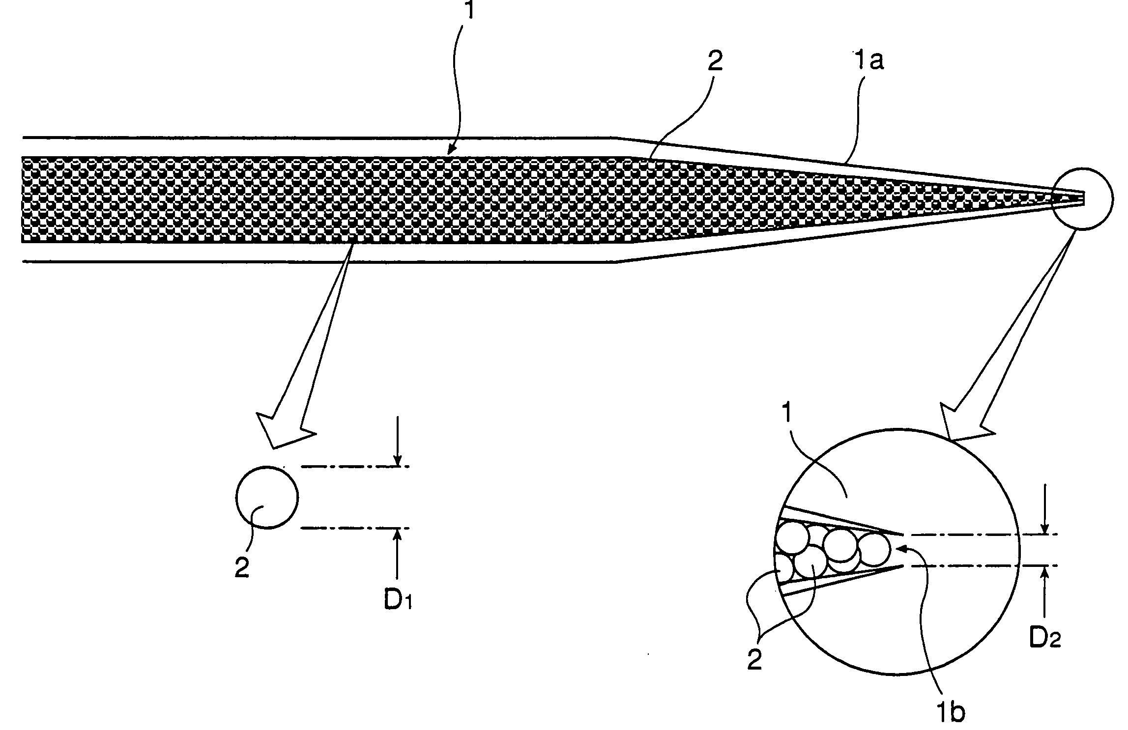
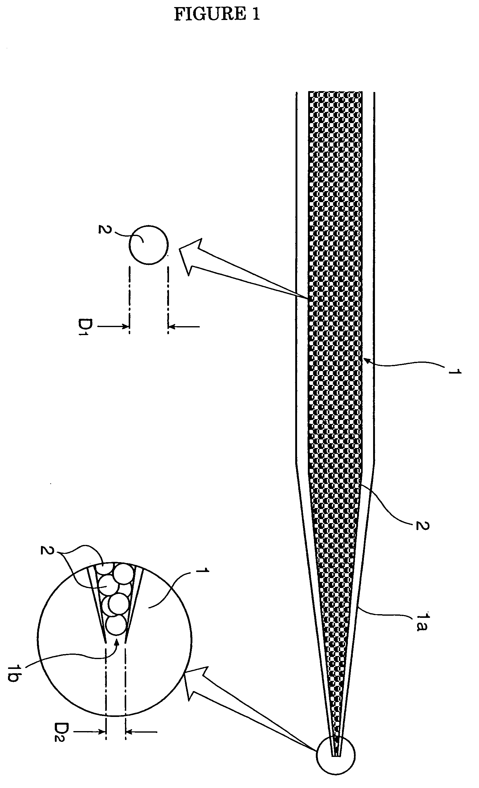
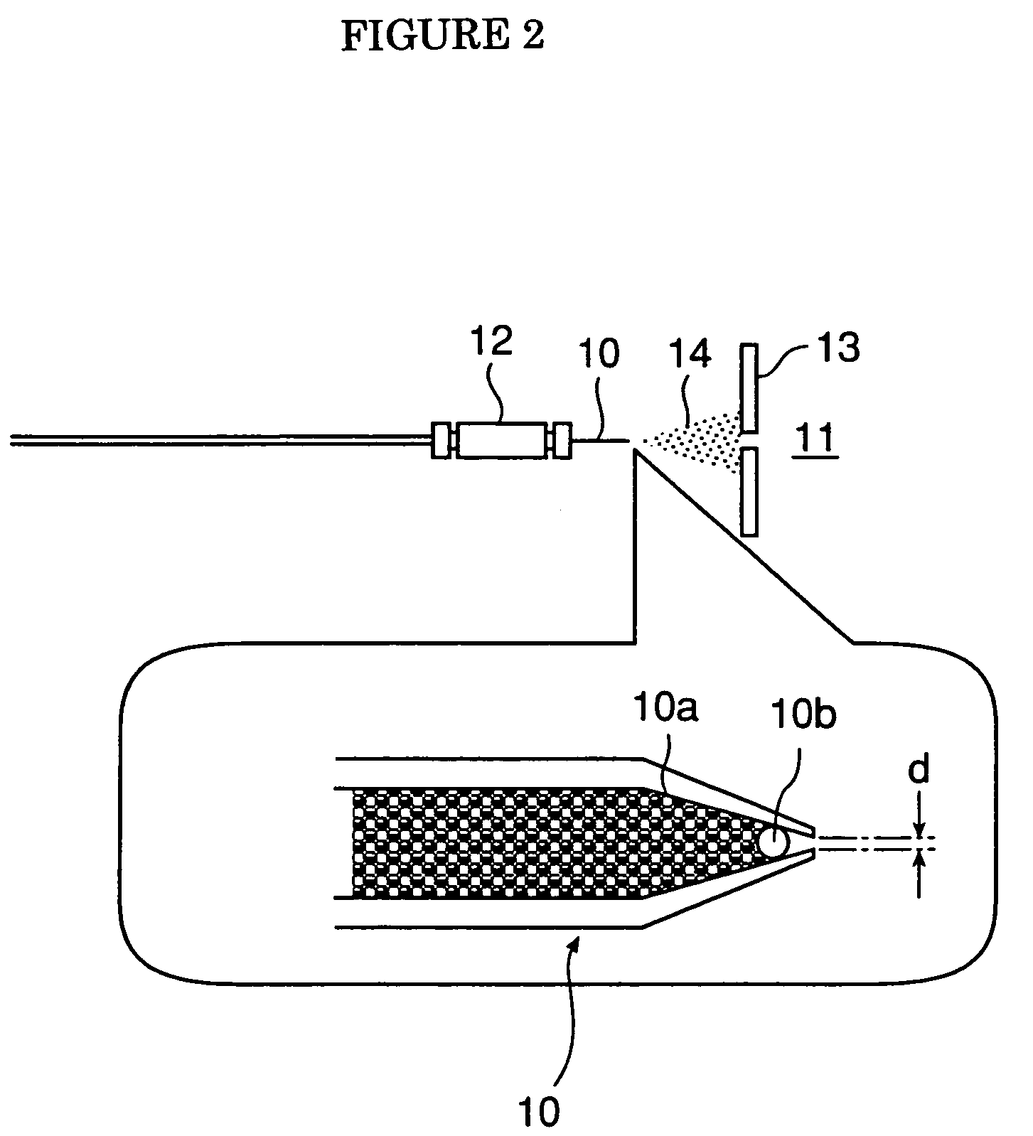
[0015] The particle size of the filler is a minimum diameter as much as it cannot be conventionally conceived. In addition, the inner diameter of the tip opening of the microspray column is small. Therefore, the discharge amount of the sample can be substantially made small, compared with the conventional one. For this reason, the particle diameter of the charged droplet formed by the spray can be miniaturized. As a result, it becomes possible to increase the efficiency of transferring the charged electron in the solvent to the sample molecule. Therefore, an increase in ionization efficiency of the sample molecule becomes possible.
[0019] With this means, it is possible to provide a mass spectrometer having high detection sensitivity and excellent ionization efficiency and a mass spectrometric method.
[0021] This technique has a technical meaning that the high sensitivity measurement of a high molecular weight compound such as peptide or protein becomes possible because of an increase in the charge number of the ion to be generated.

Problems solved by technology

However, in the conventional microspray column, the separation efficiency of a chromatograph was insufficient since the particle diameter of the filler in the column was large (generally about 50 μm).
Therefore, the discharge amount of the sample increased and the particle size of charged liquid droplets formed by the spray was also large.
As a result, in the process in which the solvent was dried and vaporized, the efficiency of transferring charged electrons to the sample molecule in the solvent was not sufficient.
In other words, the ionization efficiency of the sample molecule was insufficient.
Furthermore, the microspray column was configured such that many areas without filling with the filler were formed near the tip opening, resulting in a large discharge amount of the sample and a large particle size of the charged droplet formed with the spray.

Method used


Image

  • Microspray column, mass spectrometer, and mass spectrometry
  • Microspray column, mass spectrometer, and mass spectrometry
  • Microspray column, mass spectrometer, and mass spectrometry

Examples


example

[0039] A solution including a digestive product of a trypsin enzyme derived from human serum albumin (a molecular weight of 65,000 to 70,000) at a concentration of 50 femto mole or less was atomized from a microspray column of the present invention under the conditions in which the tip diameter of the column was 0.5 μm or less, fritless, and the particle size of the filler was 1.0 μm.

[0040] The chromatograph of the mass spectrometer obtained in the present example is shown in FIG. 4. As shown in the schematic diagram of FIG. 3, the sharp peak without reading or tailing was also obtained by the actual experimental findings as shown in the schematic diagram of FIG. 3, so that the decipherment of an amino acid sequence could be raised exponentially.

[0041]FIG. 5 shows a total amino acid sequence table (609 amino acids) of the above digestive product. In this example, the 573 amino acid sequences except of 36 amino-acid portion surrounded by a square enclosure in FIG. 5 were deciphered...


PUM


Abstract

A problem is to provide a microspray column capable of increasing the ionization efficiency, and a high sensitive mass spectrometer and a mass spectrometric method using such a microspray column. For solving this problem, we provide a column for introducing a sample in an ionization source of a mass spectrometer (ESI / MS) being designed to ionize a sample molecule with electrospray and introduce it into an analyzer, has structural features of: (1) 0.5 μm or less in an inner diameter of a tip opening of the column; (2) 0.5 μm or more and 5 μm or less in a particle size of a column filler; and (3) fritless, a microspray column having the above (1) to (3), a mass spectrometer having such a microspray column in an ionization source, and a mass spectrometric method capable of performing a nonoflow electrospray with the microspray column.

Description

TECHNICAL FIELD [0001] The present invention relates to an improved technique in mass spectrometry. In particular, the present invention relates to an improved technique of a mass spectrometer (ESI / MS) being designed to allow the introduction of a sample molecule with electrospray ionization, and a mass spectrometric method. BACKGROUND ART [0002] A mass spectrometer (hereinafter, referred to as “MS” (Mass Spectrometer)) is roughly composed of: an “ionization source” for ionizing a sample; an “analyzer” for separating ions according to the ratio of mass / charge, represented by m / ze (wherein m: mass, z: charge number, and e: unit charge); and a “detection and recording part” of ions being separated. [0003] The electrospray ionization technique generally referred to “ESI” (the abbreviation for Electrospray Ionization) is known as one of the methods of ionizing and introducing a sample molecule to an analyzer of MS. [0004] In this electrospray ionization technique, a spray is carried out...

Claims


Application Information

Patent Timeline
IPC IPC(8): H01J49/04G01N27/62
CPCH01J49/167H01J49/0013
Inventor YAMAUCHI, YOSHIONATSUME, TOHRUISOBE, TOSHIAKI
Owner NANO SOLUTION
Learn More