High-pressure fuel pump control device for engine

a control device and high-pressure fuel pump technology, which is applied in the direction of electric control, fuel injecting pump, machines/engines, etc., can solve the problems of increased output of extra signals, deterioration of durability of the actuator, and more susceptible to thermal damage of the solenoid as one component of the actuator, so as to improve the durability of the high-pressure fuel pump, improve the robustness, and satisfy the effect of combustion

Active Publication Date: 2005-06-16
HITACHI ASTEMO LTD
View PDF8 Cites 42 Cited by
  • Summary
  • Abstract
  • Description
  • Claims
  • Application Information

AI Technical Summary

Benefits of technology

[0028] With the high-pressure fuel pump control device for the engine according to the present invention, the outputting of the solenoid drive signal is started during the period from the operation start to the point in time at which it becomes possible to output the solenoid drive signal in the predetermined crank angle phase. Also, the outputting of the solenoid drive signal is stopped when the fuel pressure in the common rail has boosted over the predetermined value per unit time, or when a pressure difference with respect to the pressure at the operation start has exceeded a predetermined value. Therefore, the fuel pressure can be positively boosted to a required level, and satisfactory combustion is realized with improved robustness. Further, a total energization time of the solenoid at the startup can be cut as compared with the known techniques. It is hence possible to increase durability of the high-pressure fuel pump and to reduce current consumption.
[0029] In addition, since the output start timing of the solenoid drive signal is delayed from the operation start timing, it is possible to further cut the total energization time of the solenoid, increase durability of the high-pressure fuel pump, and reduce current consumption.

Problems solved by technology

In addition, there is a risk that a solenoid as one component of the actuator is more susceptible to a thermal damage or other troubles, and durability of the actuator deteriorates.
In the case where actual variations are small, extra signals are outputted and current consumption is increased.
However, a particular consideration is not paid to determination as to whether the other type of control is performed before the crank angle phase becomes definite.
Additionally, any of the above-described known techniques has a possibility that, because the pump discharge stroke includes a period for outputting a valve opening signal (to turn off the driving output) for the purpose of duty control-, the pump inlet valve may fail to close, namely the-positive pressure boosting is not ensured.

Method used


Image

  • High-pressure fuel pump control device for engine
  • High-pressure fuel pump control device for engine
  • High-pressure fuel pump control device for engine

Examples


Embodiment Construction

[0049] Embodiments of a high-pressure fuel pump control device for an engine according to the present invention will be described below with reference to the drawings.

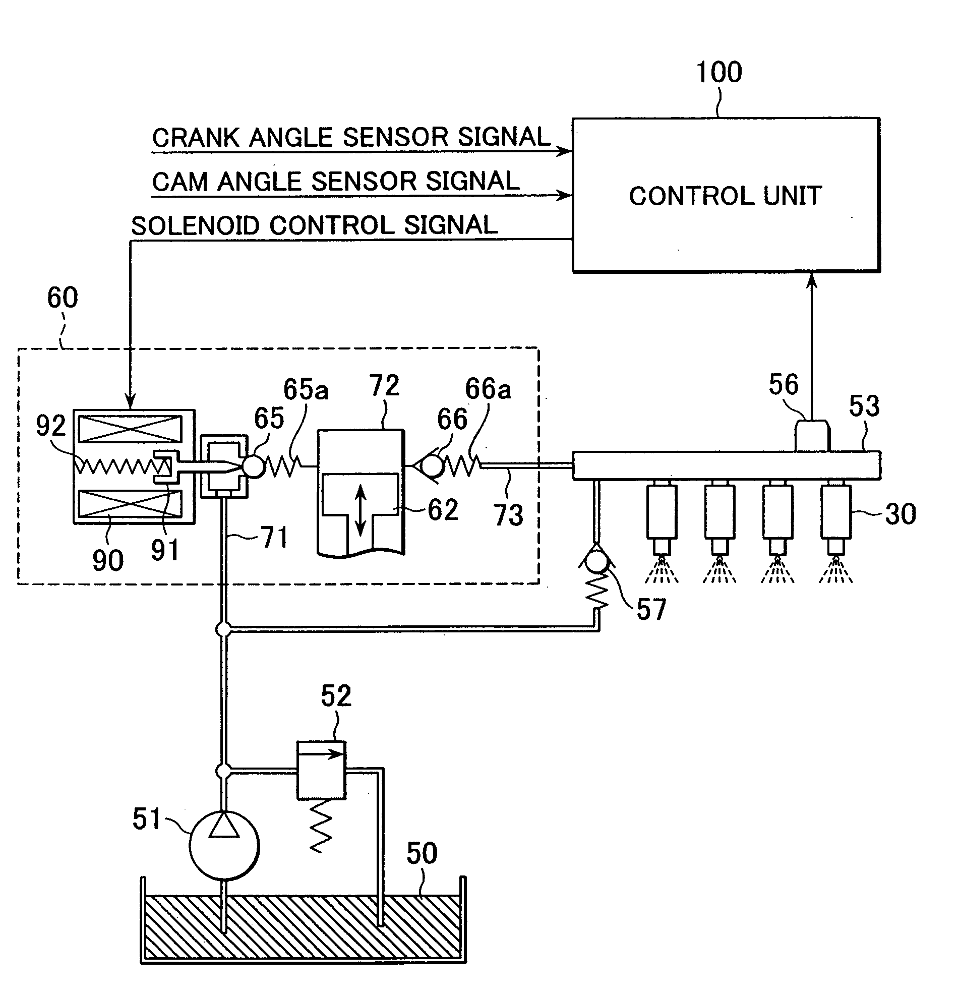
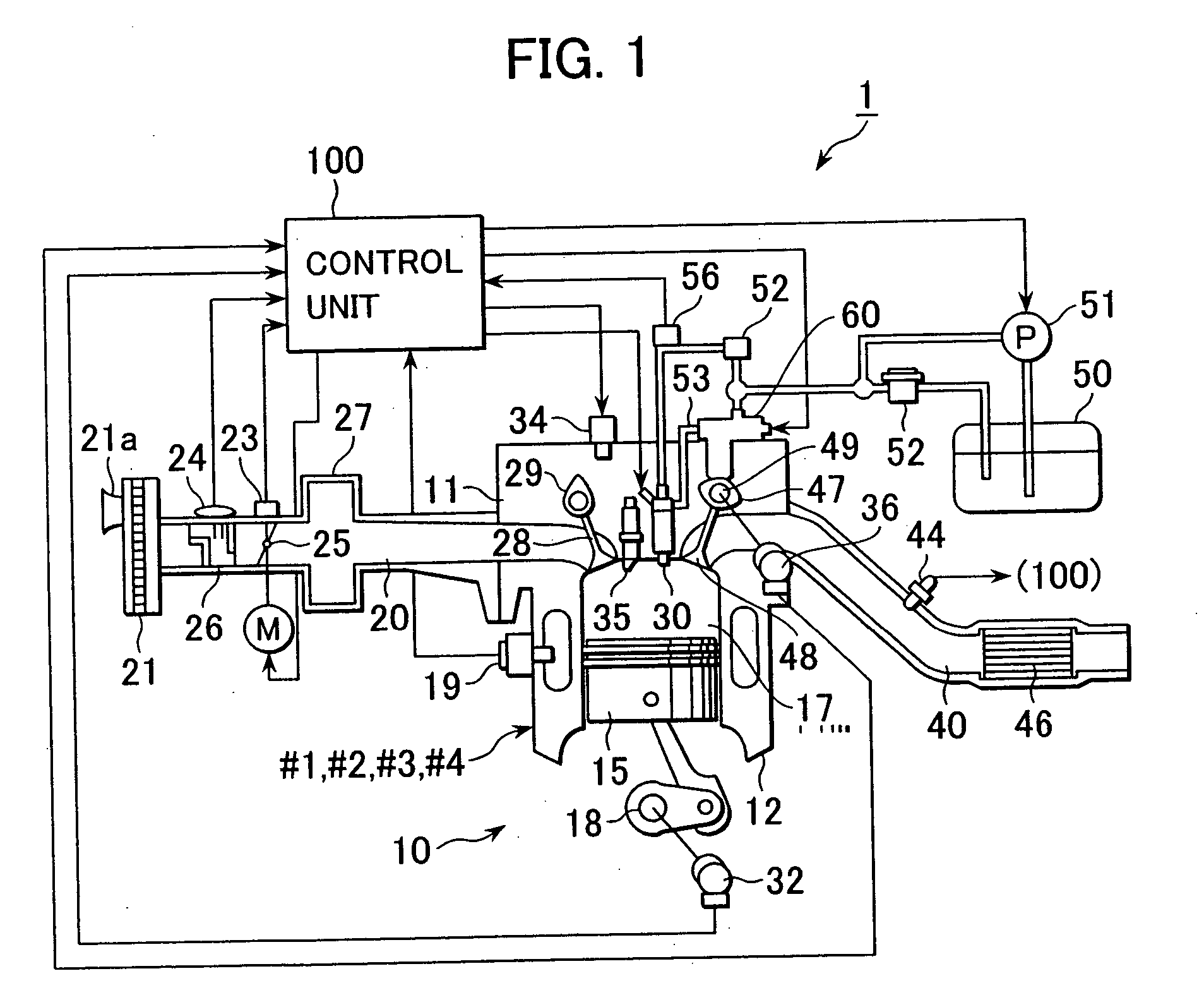
[0050]FIG. 1 is an overall schematic view of one embodiment of the high-pressure fuel pump control device according to the present invention, along with one example of a vehicle-loaded in-cylinder injection engine to which the high-pressure fuel pump control device is applied.

[0051] An in-cylinder injection engine 10 shown in FIG. 1 is, for example, a 4-cylinder in-line engine having four cylinders #1, #2, #3 and #4. The in-cylinder injection engine 10 comprises a cylinder head 11, a cylinder block 12, and a piston 15 slidably fitted in the cylinder block 12. A combustion chamber 17 is defined above the piston 15. An ignition plug 35 supplied with a high voltage from an ignition coil 34 and a fuel injector valve 30 for directly injecting fuel into the combustion chamber 17 are disposed so as to face the combustion ch...


PUM


Abstract

A high-pressure fuel pump control device capable of reducing current consumption, increasing pump durability, and promoting a rise of fuel pressure from startup. The high-pressure fuel pump control device comprises a fuel injector valve for directly injecting fuel in a common rail into a combustion chamber and a high-pressure fuel pump for feeding the fuel under pressure to the common rail. The high-pressure fuel pump comprises a pressurization chamber, a plunger for pressurizing the fuel in the pressurization chamber, a fuel passage valve disposed in the pressurization chamber, and an actuator for actuating the fuel passage valve. The control device includes a control unit for executing output control of a drive signal for the actuator to vary a discharge rate of the high-pressure fuel pump. The control unit starts outputting of the actuator drive signal during a period from operation start to a point in time at which the actuator drive signal becomes able to issue in a predetermined crank angle phase, and sets timing of stopping the outputting of the actuator drive signal to a point in time at which the fuel pressure in the common rail has boosted over a predetermined value per unit time.

Description

BACKGROUND OF THE INVENTION [0001] 1. Field of the Invention [0002] The present invention relates to a high-pressure fuel pump control device for an engine, and more particularly to a high-pressure fuel pump control device capable of variably adjusting a discharge amount of high-pressure fuel that is fed under pressure to a fuel injector valve. [0003] 2. Description of the Related Art [0004] From the viewpoint of environmental protection, there are at present a demand in the field of automobiles for reducing particular substances contained in automobile exhaust gas, such as carbon monoxide (CO), hydrocarbons (HC), and nitrogen oxides (NOx), i.e., for improving exhaust emission characteristics and enhancing fuel economy. To meet such a demand, a direct injection engine (in-cylinder injection engine) is under development. In the direct injection engine, improvements in exhaust emission characteristics and hence in engine output are intended by directly injecting fuel from a fuel injec...

Claims


Application Information

Patent Timeline
Patent Type & Authority Applications(United States)
IPC IPC(8): F02M51/00F02D41/06F02D41/20F02D41/38F02D45/00F02M59/10F02M59/20F02M59/36F02M63/02
CPCF02D41/062F02D41/3845F02D2200/0602F02M2200/502F02M59/102F02M59/366F02M63/0225F02D2250/31
Inventor OKAMOTO, TAKASHI
Owner HITACHI ASTEMO LTD
Why Eureka
Try Eureka