Acid gas scrubbing apparatus and method

a technology of acid gas and scrubbing apparatus, which is applied in the direction of combustible gas production, combustible gas purification/modification, separation processes, etc., can solve the problems of reducing the efficiency of acid gas removal, and toxic to the human body. , to achieve the effect of improving the ability of acid gas removal and increasing energy efficiency

Inactive Publication Date: 2005-06-23
SU QINGQUAN +4
View PDF7 Cites 105 Cited by
  • Summary
  • Abstract
  • Description
  • Claims
  • Application Information

AI Technical Summary

Benefits of technology

[0012] The present invention has been made in view of the above, and it is therefore an object of the present invention to provide an acid gas scrubbing apparatus and method which can increase ene...

Problems solved by technology

However, even the trace amount of acid gases are toxic to the human body, and such acid gases are corrosive to gas treatment facilities and poisonous to various catalysts, and hence it is necessary to remove such acid gases.
However, when a high-temperature gas is scrubbed in a wet-type scrubber operated at atmospheric pressure, heat recovered by the scrubbing liquid from the gas to be scrubbed is low temperature heat having a temperature of 100° C. or lower, and hence in most cases, such recovered heat is discharged to the atmosphere in a cooling tower or the like, and is not utilized effectively.
In recent years, dioxins generated in incinerators are one of society's problems, and it is said that the main cause of the generation of dioxins is a resynthesis reaction of dioxins in the temperature range of 250 to 500° C. in the presence of catalytic incineration ash.
Because such fluidizing gas is also used as an oxidizing agent, in some cases where air is used as a fluidiz...

Method used


Image

  • Acid gas scrubbing apparatus and method
  • Acid gas scrubbing apparatus and method
  • Acid gas scrubbing apparatus and method

Examples


first embodiment

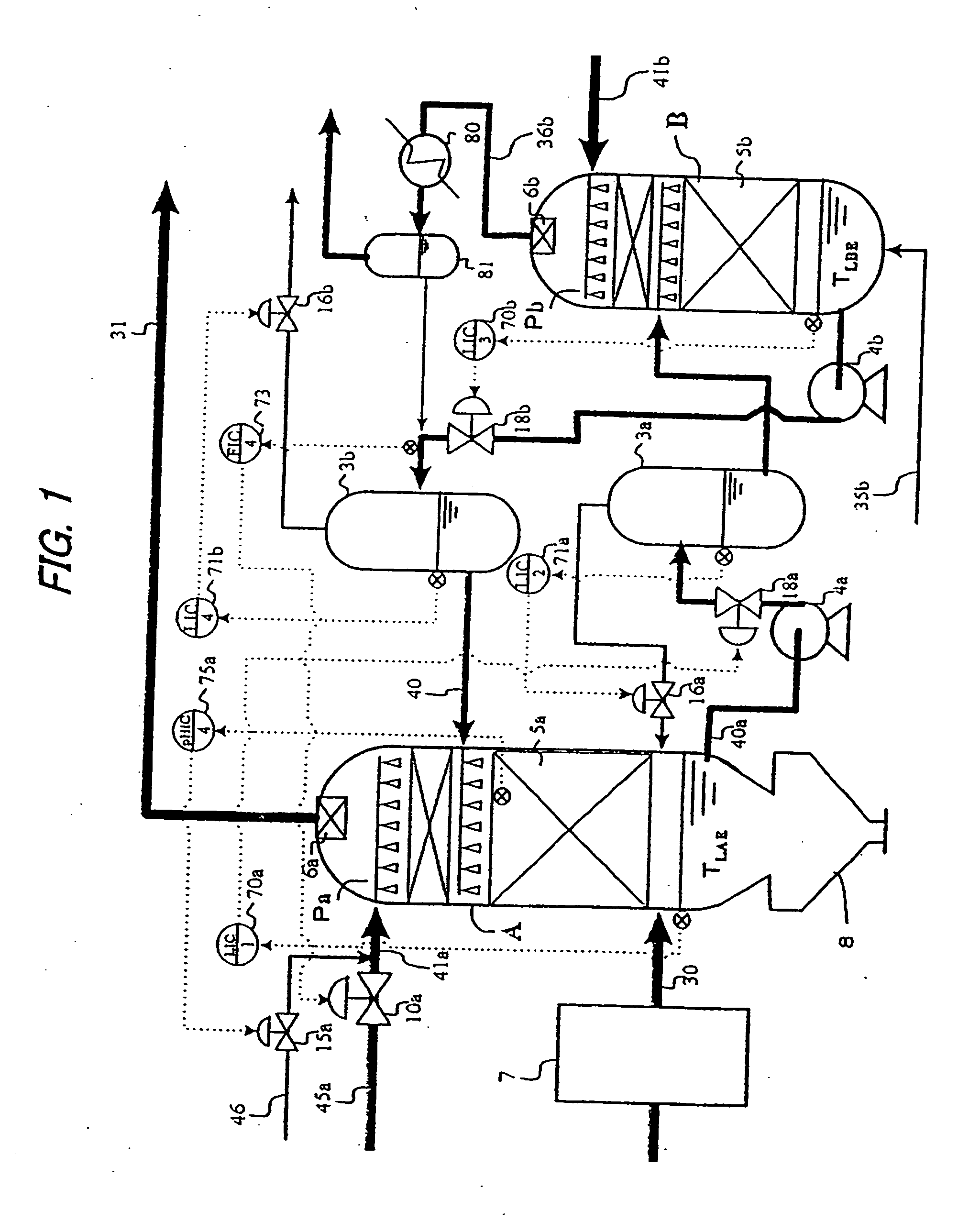
[0047] An embodiment of the present invention will be described with reference to FIG. 1 showing the present invention. In embodiments shown in FIGS. 1 through 20, like or corresponding parts or elements are denoted by like or corresponding reference numerals throughout the views, and repetitive description is eliminated. A gas 30, to be scrubbed, introduced from a lower part of a gas scrubber A into the gas scrubber A is brought into contact with a gas scrubbing liquid 40 containing alkaline agent supplied from an upper part of the gas scrubber A into the gas scrubber A and is cooled, and acid gases such as hydrogen sulfide, carbonyl sulfide, hydrogen chloride, sulfur oxides, nitrogen oxides, and carbon dioxide and dust are removed from the gas 30.

[0048] In the case where the gas to be scrubbed is exhaust gas generated by incineration of wastes containing chlorine such as municipal wastes, the temperature of the gas, to be scrubbed, supplied to the gas scrubber A is normally about ...

second embodiment

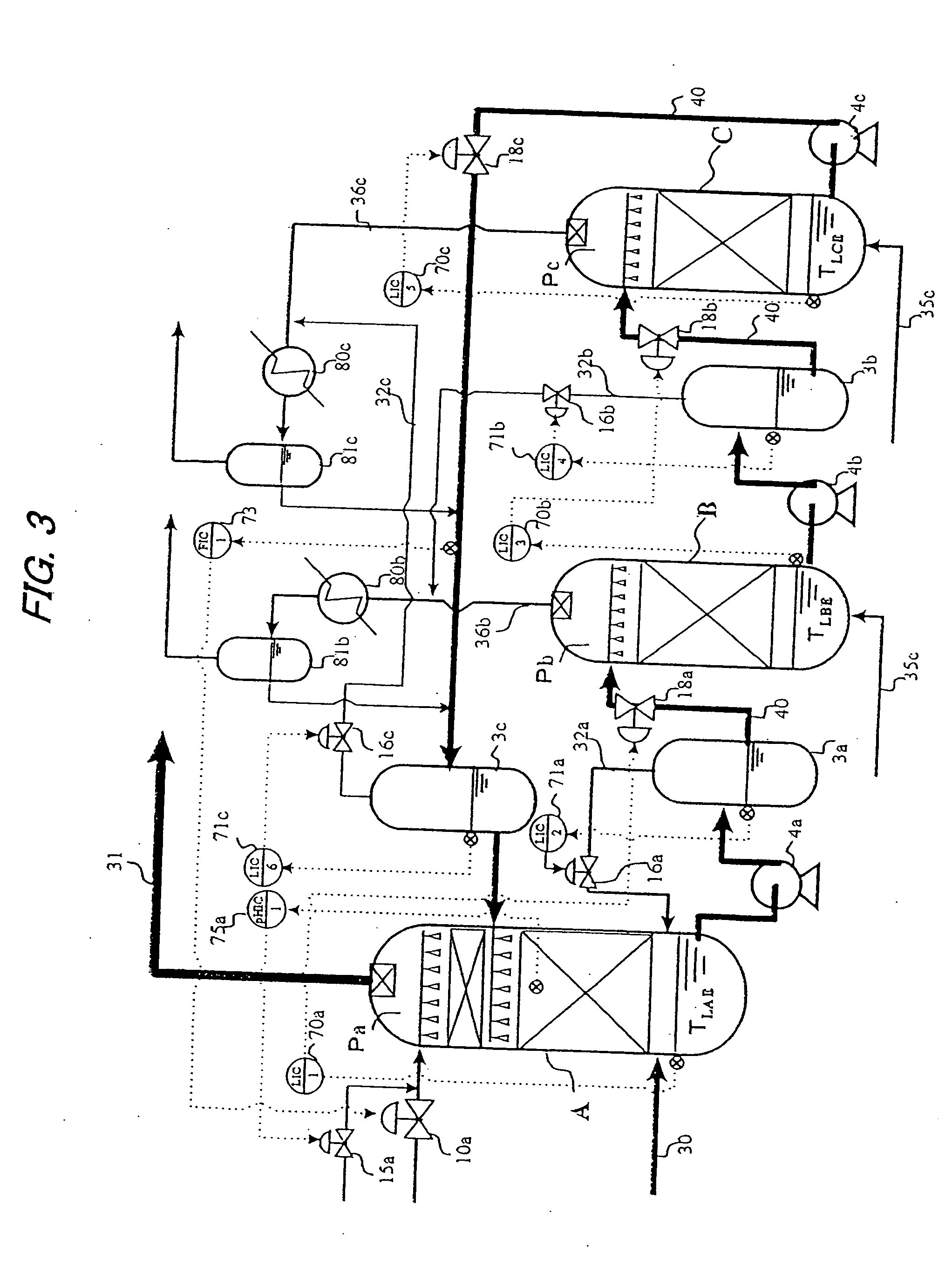
[0091]FIG. 3 shows the present invention in which regeneration of alkaline agent is performed in a two-stage regenerator comprising the regenerator B and a second regenerator C to enhance a regeneration function of alkaline agent. The function of equipment up to the first regenerator B is the same as explained in FIG. 1. The scrubbing liquid withdrawn from the first regenerator B is supplied to the second regenerator C. A regenerating gas 35c having components according to the purposes is supplied to the second regenerator C as with the regenerator B, and the regenerating gas 35c is brought into contact with the scrubbing liquid, and then the gas which accompanies saturated steam and desorbed carbon dioxide is discharged to the outside of the system as a regenerator vent gas 36c. The structure of the second regenerator C is basically the same as that of the regenerator B, and the scrubbing liquid withdrawn from the second regenerator C is returned to the gas scrubber A again.

[0092] ...

third embodiment

[0152]FIG. 14 shows the present invention in which a gas scrubber comprises a two-stage scrubber comprising a first gas scrubbing section A′ and a second gas scrubbing section A2, and a scrubbing liquid regenerator comprises a two-stage regenerator comprising a first regenerator B and a second regenerator C, whereby an alkaline regeneration function of the scrubbing liquid and an acid gas removing function of the gas to be scrubbed are further enhanced. A gas 30, to be scrubbed, supplied to the first gas scrubbing section A′ is brought into contact with a first scrubbing liquid 82b in a countercurrent flow, and the gas 30 to be scrubbed is cooled by the first scrubbing liquid 82b and strong acid gases such as hydrogen chloride are absorbed in the first scrubbing liquid 82b, and dust components in the gas are entrapped in the first scrubbing liquid 82b. Next, the gas to be scrubbed which has been led from the first gas scrubbing section A′ to the second gas scrubbing section A2 is br...


PUM

PropertyMeasurementUnit
Temperatureaaaaaaaaaa
Combustionaaaaaaaaaa

Abstract

An acid gas scrubbing apparatus and method brings a gas, to be scrubbed, containing carbon dioxide into contact with a gas scrubbing liquid containing alkaline agent and cooled, and acid gases in the gas are removed. A gas scrubber removes acid gases in a gas, to be scrubbed, containing carbon dioxide by bringing the gas to be scrubbed into contact with a gas scrubbing liquid containing alkaline agent. A scrubbing liquid regenerator regenerates and cools the gas scrubbing liquid by bringing the gas scrubbing liquid into contact with a regenerating gas having components different from the gas scrubbing liquid and the gas to be scrubbed. A circulating device is provided between the gas scrubber and the scrubbing liquid regenerator for circulating the scrubbing liquid.

Description

[0001] This application is a continuation application of Ser. No. 10 / 031,397, filed Jan. 18, 2002, which is a National Stage Application of International Application Serial No. PCT / JP00 / 04857, filed Jul. 19, 2000.TECHNICAL FIELD [0002] The present invention relates to an acid gas scrubbing apparatus and method, and more particularly to an acid gas scrubbing apparatus and method in which a gas, to be scrubbed, containing carbon dioxide is brought into contact with a gas scrubbing liquid containing alkaline agent and cooled, and acid gases in the gas are removed. BACKGROUND ART [0003] In the case where combustible wastes are combusted or gasified, a combustion gas or a produced gas generated by combustion or gasification (hereinafter referred to as “gas to be scrubbed”) contains acid gases such as hydrogen chloride, sulfur oxides, nitrogen oxides and hydrogen sulfide. In many cases, the gas to be scrubbed contains a trace amount of these acid gases in the order of ppm. However, even t...

Claims


Application Information

Patent Timeline
IPC IPC(8): B01D53/14B01D53/62C10J3/82C10K1/08C10K1/12
CPCB01D53/1425C10J2200/158B01D53/1475B01D53/62C10J3/721C10J3/82C10K1/08C10K1/12Y02C10/04Y02C10/06C10K1/003C10K1/024C10K1/026C10K3/04C10J2300/1621C10J2300/1646C10J2300/1662C10J2300/1807B01D53/1456Y02C20/40Y02P20/151B01D53/14B01D53/40
Inventor SU, QINGQUANMIYOSHI, NORIHISANARUSE, KATSUTOSHIOSHITA, TAKAHIROKINOSHITA, KAZUO
Owner SU QINGQUAN
Why Eureka
Try Eureka