Alkaline zinc-nickel alloy plating compositions, processes and articles therefrom
- Summary
- Abstract
- Description
- Claims
- Application Information
AI Technical Summary
Benefits of technology
Problems solved by technology
Method used
Image
Examples
examples
[0090] The following examples illustrate the aqueous alkaline plating baths of the invention. The amounts of the components in the following examples are in grams / liter. Unless otherwise indicated in the specification and claims, all parts and percentages are by weight, temperatures are in degrees centigrade, and pressures are at or near atmospheric pressure. In the following examples, the source of zinc ions is zinc oxide in caustic soda, and the source of nickel ions is nickel sulfate.
Electrolytes:
[0091] In the examples, five different alkaline electrolytes and two acid electrolytes are prepared. These electrolytes are used with various combinations of grain refiners in accordance with the invention, or without such grain refiners or in the acid electrolytes, in comparative examples.
Electrolyte one (E1):ZnO0.154 mol / dm3Triethanolamine0.035 mol / dm3Tetraethylenepentamine0.099 mol / dm3Nickel ion from nickel sulfate0.026 mol / dm3Quadrol 0.04 mol / dm3NaOH 3.0 mol / dm3
[0092]
Electrolyte...
example auxiliary
Brightening Agents
[0100] In some of the Examples, one or more of the following auxiliary brightening agents were added. However, there are a large variety of such compounds, and those included in these Examples are exemplary and are not intended to limit the invention in any way. Those of ordinary skill in the art can identify suitable auxiliary brighteners in addition to those listed below and those identified elsewhere in the application.
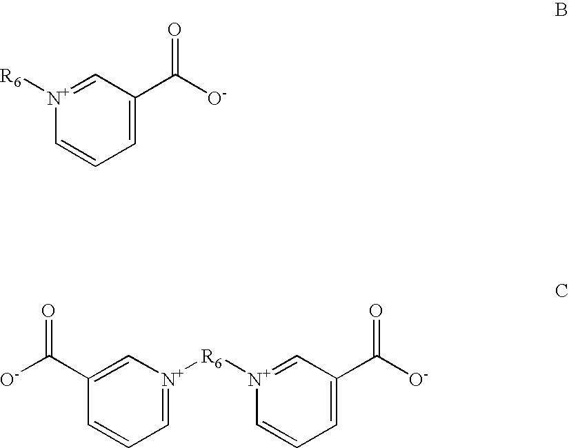
Brighteningagent codeClassBrightening AgentBA1Polymeric aminesCondensation product ofpiperazine, guanidine, formalin,and epichlorohydrinBA2Polymeric aminePolyethylene imineBA3Aromatic pyridiniumPyridinium propyl sulfonatecompoundBA4Aromatic pyridiniumN-benzyl-3-carboxy pyridiniumcompoundchlorideBA5Aromatic pyridiniumTrigonellinecompoundBA6Acetylenic compoundGolpanol PSBA7Acetylenic compoundPropargylalcoholBA8Acetylenic compoundEthyleneglycolpropargylalcoholether
examples 1-34
[0101] The following table provides examples of the present invention and of several comparative examples. In the table, the following headings have the following meanings:
[0102]“E'lyte” is the electrolyte used, selected from E1-E8 as defined above.
[0103]“% E” is the percent elongation, may also be referred to as “bendability” and is determined by use of a cylindrical mandrel test (e.g., ISO 8401, paragraph 4.4).
[0104]“D. of comp. Decoh.” is the diameter of a cylindrical mandrel at which a sample bent around the mandrel forms cracks observable by use of a 10× magnifying loop, as a result of compressive decohesion, as described above.
[0105]“Throwing power” is determined by use of a Haring Blum cell, in which two cathodic panels are simultaneously plated using a single anode. The two cathodic panels are set at different lengths or distances from the anode. The % throwing power is determined from the equation % TP=100 (L−R) / L, where L is the far-to-near cathode distance ratio and R...
PUM
| Property | Measurement | Unit |
|---|---|---|
| Density | aaaaa | aaaaa |
| Density | aaaaa | aaaaa |
| Molar density | aaaaa | aaaaa |
Abstract
Description
Claims
Application Information
 - R&D
- Intellectual Property
- Life Sciences
- Materials
- Tech Scout
- Unparalleled Data Quality
- Higher Quality Content
- 60% Fewer Hallucinations
Browse by: Latest US Patents, China's latest patents, Technical Efficacy Thesaurus, Application Domain, Technology Topic, Popular Technical Reports.
© 2025 PatSnap. All rights reserved.Legal|Privacy policy|Modern Slavery Act Transparency Statement|Sitemap|About US| Contact US: help@patsnap.com


