However, since the IGCC technology is oriented toward the complete gasification of the coal, the gasification temperature needs to be increased to a temperature range for melting the ash, resulting in many problems related to the
discharge of the
molten slag and the durability of the
refractory material.
Furthermore, because part of the
heat energy is consumed for melting the ash, although the generated gases are discharged in such a state that they have a high temperature, the temperature of the generated gases must be lowered for gas purification to a temperature of, for example, about 450° C., causing a very large
sensible heat loss.
Another problem is that it is necessary to supply
oxygen or
oxygen-enriched air in order to achieve a high temperature stably.
For these reasons, the
net energy conversion efficiency is not increased, and no technology is available for generating
electric energy with high efficiency using the generated gases.
However, the two-
bed pyrolysis reactor system has not actually been commercialized as a large-scale
plant because of problems relating to the handling of high-temperature particles, such as obtaining a sufficient amount of particle circulation between the gasification furnace and the char combustion furnace, controlling of the circulating amount of particles, and stable operation, and problems relating to operation, such as a failure in
temperature control of the char combustion furnace independently of other operations.
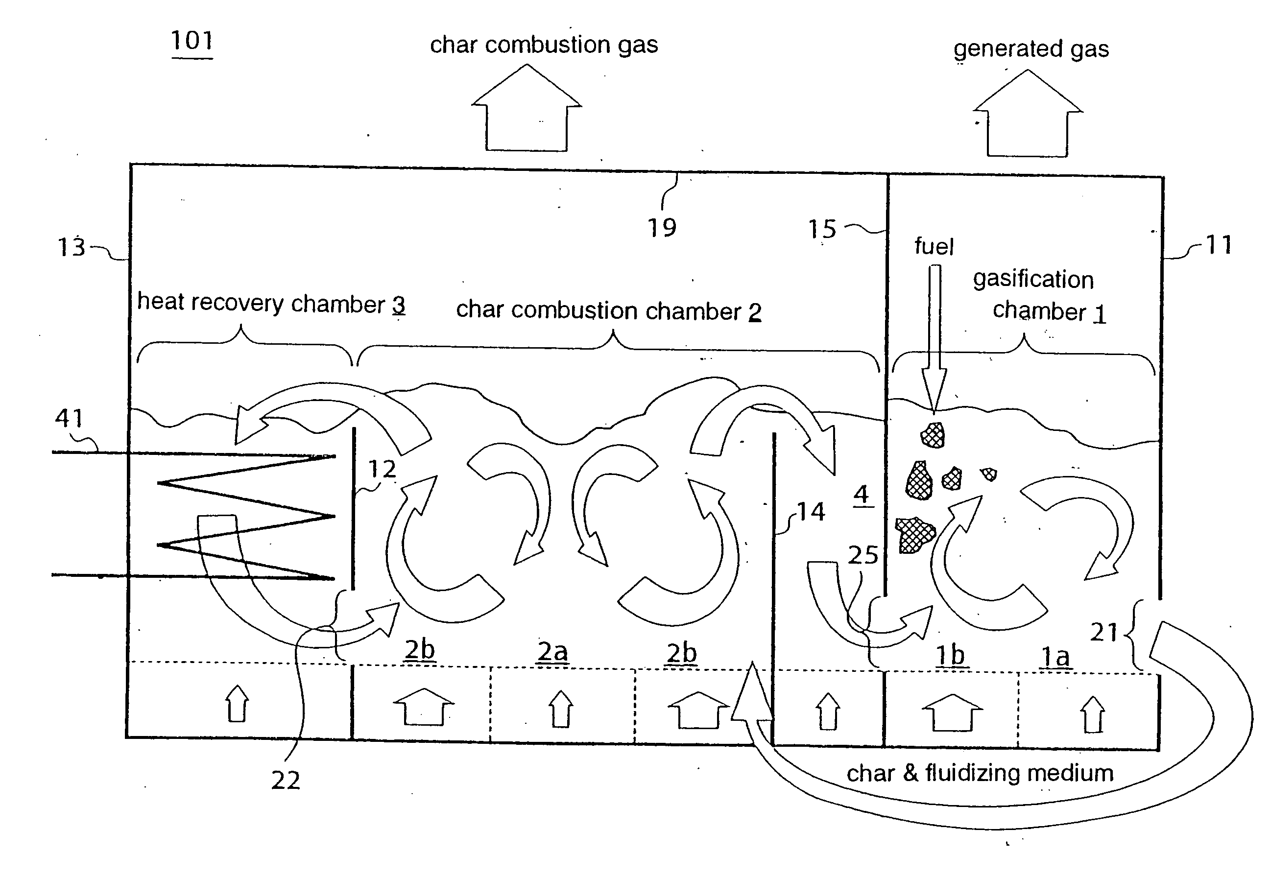
However, inasmuch as the proposed
system delivers the entire combustion gases discharged from the char combustion furnace to the gasification furnace, it goes against the principle of the
power generation system using an improved pressurized fluidized-
bed furnace that it should be obtained generated gases in as small an amount as possible and having as high a calorific value as possible.
Conversely, if the amount of char combustion gases becomes smaller, then the
fluidization in the gasification furnace becomes insufficient or the temperature of the gasification furnace is lowered, resulting in a need for supplying air to the gasification furnace.
When the
system undertakes a
low load, as the combustion gases are cooled by the
heat transfer pipes exposed over the bed, the temperature of the gasification furnace and the fluidizing gas velocity changes, affecting the gasifying
reaction rate to make it difficult to operate the system stably.
Nevertheless, the integrated gasification furnace is problematic in that since no complete seal is provided between char combustion gases and generated gases, the combustion gases and the generated gases may be mixed with each other, degrading the properties of the generated gases, if the
pressure balance between the gasification chamber and the char combustion chamber is not kept well.
However, since a small amount of char is produced by the
pyrolysis of municipal wastes, it is highly likely not to obtain a char combustion heat required to superheat the steam.
According to an available conventional method, the fluidizing medium has to be mechanically delivered by a conveyor or the like, resulting in problems such as the difficulty in handing high-temperature particles and a large
sensible heat loss.

