Adaptive dead-time controller

Inactive Publication Date: 2005-07-07
LEADTREND TECH
View PDF3 Cites 20 Cited by
  • Summary
  • Abstract
  • Description
  • Claims
  • Application Information

AI Technical Summary

Benefits of technology

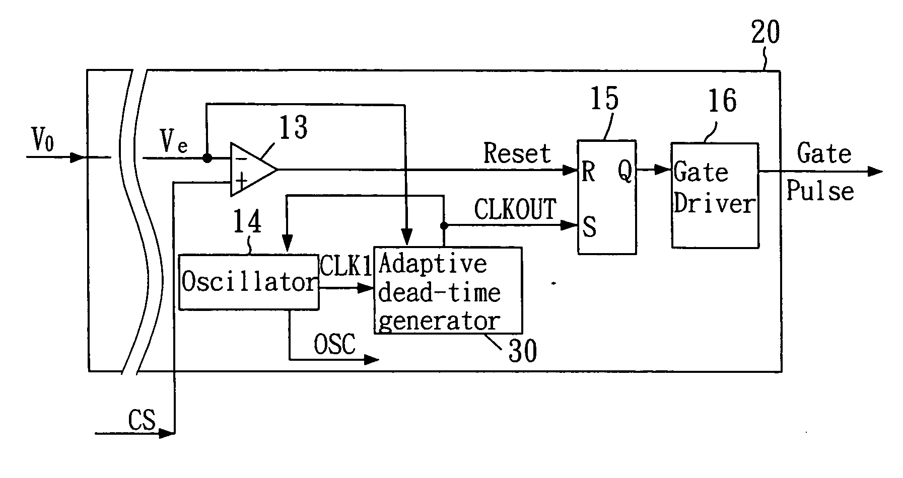
[0013] The present invention provides an adaptive dead-time controller for adjusting an operating frequency of a power converter according to a load condition, comprising: a reference voltage generator for providing a reference voltage; an error amplifier for comparing an output voltage with the reference voltage, then outputting an error voltage, the output voltage being proportional to the load condition; a comparator for comparing the error voltage with a switch voltage then outputting a reset signal; an oscillator for providing a clock signal; an adaptive dead-time generator for adjusting an oscillation signal corresponding to the clock signal according to the load condition, then outputting the adjusted oscillation signal; and a flip-flop for outputting a gate pulse according to the reset signal and the oscillation signal, wherein the gate pulse is adapted to adjust the function of the power converter, when the load condition is light, a rising edge of the oscillation signal is delayed by a dead-time from a rising edge of the clock signal. Because the cycle time of the oscillation signal is adjusted based on the output voltage corresponding to a load condition, if the load condition presents a low load or no load condition, the dead-time will add to the oscillation signal and the power consumption of the power converter will be reduced.

Problems solved by technology

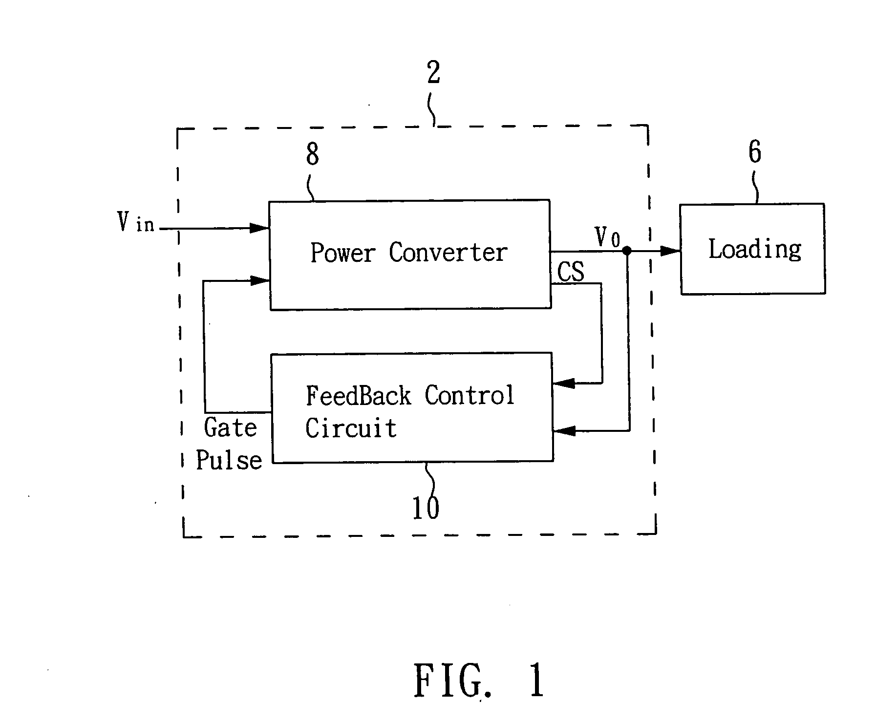
Gate pulses with a fixed frequency cause the power converter 8 to have high switching losses during light load or no load conditions.

Method used


Image

  • Adaptive dead-time controller
  • Adaptive dead-time controller
  • Adaptive dead-time controller

Examples


first embodiment

[0036] As shown in FIG. 11, a first embodiment of an adaptive dead-time generator 40 comprises a schottky diode 401, an adder 402, a voltage controlled current source 403, a standard current source 404, an inverter 302, a switch transistor 304, a capacitor 305, and a comparator 306. As shown, the converting circuit 301 and the current source 303 are replaced by the schottky diode 401, the adder 402, the voltage controlled current source 403 and the standard current source 404. If a minor voltage drop of the schottky diode 401 is ignored, the schottky diode 401 keeps the error voltage Ve at the highest voltage Va; the adder 402 adds a negative default voltage Vb and the error voltage Ve, and then controls a supply current of the voltage controlled current source 403 according to the result. For example, the supply current of the current source 403 may be K times the result of the adder 402, wherein K=I2−I1 / Va−Vb. Please refer to FIG. 12. Under heavy load conditions, the voltage contr...

second embodiment

[0037] As shown in FIG. 13, a second embodiment of the adaptive dead-time controller 50 comprises a hysteresis comparator 501, a controlled current source 502, a standard current source 503, an inverter 302, a switch transistor 304, a capacitor 305, and a comparator 306. As shown, the converting circuit 301 and the current source 303 are replaced by the hysteresis comparator 501, the controlled current source 502, and the standard current source 503. The hysteresis characteristics of the hysteresis comparator 501 are adapted to reduce the sensitivity of the switching of the error voltage Ve to avoid errors caused by noise. When the error voltage Ve is larger than a high voltage Vc, a signal output from the hysteresis comparator 501 enables the controlled current source 502; when the error voltage Ve is smaller than a low voltage Vd, a signal output from the hysteresis comparator 501 disables the controlled current source 502. If the error voltage Ve is within a hysteresis region bet...


PUM


Abstract

An adaptive dead-time controller is provided to improve a conversion efficiency of a power converter at a low / no load condition. The adaptive dead-time controller has a reference voltage generator, an error amplifier, a comparator, an oscillator, an adaptive dead-time generator and a flip-flop. The adaptive dead-time controller outputs a gate pulse according to an output voltage and an oscillation. When power converter is at a low / no load condition, the adaptive dead-time generator delays a rising edge of an oscillation signal by a dead-time from a rising edge of a clock signal, so the frequency of the gate pulse and the power consumption of the power converter are reduced.

Description

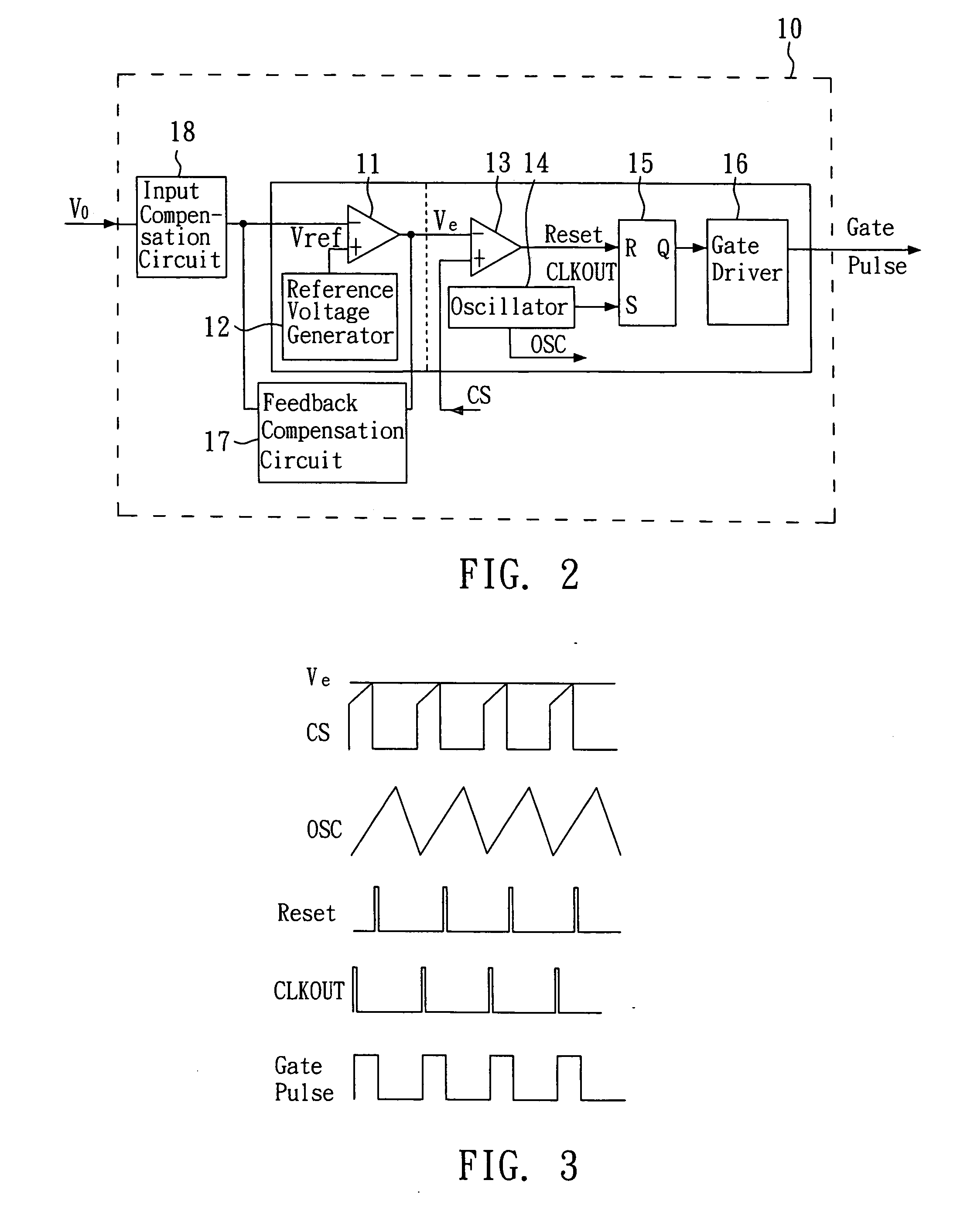
BACKGROUND OF THE INVENTION [0001] 1. Field of the Invention [0002] The present invention relates to an adaptive dead-time controller and, more particularly, to an adaptive dead-time controller for improving the conversion efficiency of a power converter in light load or no load conditions. [0003] 2. Description of the Related Art [0004] As shown in FIG. 1, in a power supply circuit 2, a power converter 8 is used for receiving an external input voltage Vin and providing an output voltage Vo to a load device 6. A feedback control circuit 10 outputs a proper gate pulse to the power converter 8 according to the output voltage Vo and a current sense (CS) level for providing more or less power to a load device 6. For example, when a load device 6 presents a heavy load, the feedback control circuit 10 requires the power converter 8 to provide a higher output power to satisfy the power consumption of a load device 6; when a load device 6 presents a light load, the feedback control circuit ...

Claims


Application Information

Patent Timeline
IPC IPC(8): G05F1/40G05F1/66H02M1/38
CPCH02M1/38
Inventor KUO, MING-YINGLEE, HUNG-TA
Owner LEADTREND TECH
Why Eureka
Try Eureka