System and method for endoluminal grafting of bifurcated and branched vessels

Inactive Publication Date: 2005-07-14
CARDIAQ VALVE TECH
View PDF52 Cites 155 Cited by
  • Summary
  • Abstract
  • Description
  • Claims
  • Application Information

AI Technical Summary

Benefits of technology

[0033] It is accordingly a primary object of the present invention to extend the benefit of endoluminal grafting t

Problems solved by technology

Indeed, many patients who are diagnosed with aortic aneurysms are relatively high-risk patients and may be classed as poor-risk for traditional surgery.
If allowed to remain untreated, the aneurysm will surely dissect or rupture, causing a catastrophic event leading to significant risk of death to the patient.
The traditional surgery in itself incurs significant risk of morbidity and mortality to the patient, due to its inherently extensive nature, which includes excessive blood loss, intra-operative heart attacks, and organ system ischaemias due to the cross-clamping of the aorta, which is an inherent part of the procedure.
At the present time, endoluminal grafting can be performed in patients with aneurysms isolated to the infra-renal position or at the juxta-renal position with great benefit to the high-risk patients, but is not extendable to a large population of patients that suffer with aneurismal disease of the aorta that involves its major branches.
Unfortunately, not all the patients diagnosed with aortic aneurysm are presently considered to be candidates for endovascular grafting.
This is largely due to the fact that most of the endovascular grafting systems are not designed for use in regions of the aorta from which side branches (i.e., carotids, innominate, subclavian, intercostals, superior mesenteric, celiac, renal) extend.
The deployment of an endovascular graft within the regions of the aorta from which the branch anatomic conduits emanate presents an additional technical challenge, because in those cases, the endovascular graft must be designed such that it can be inserted, aligned, and deployed with discrete

Method used


Image

  • System and method for endoluminal grafting of bifurcated and branched vessels
  • System and method for endoluminal grafting of bifurcated and branched vessels
  • System and method for endoluminal grafting of bifurcated and branched vessels

Examples


first embodiment

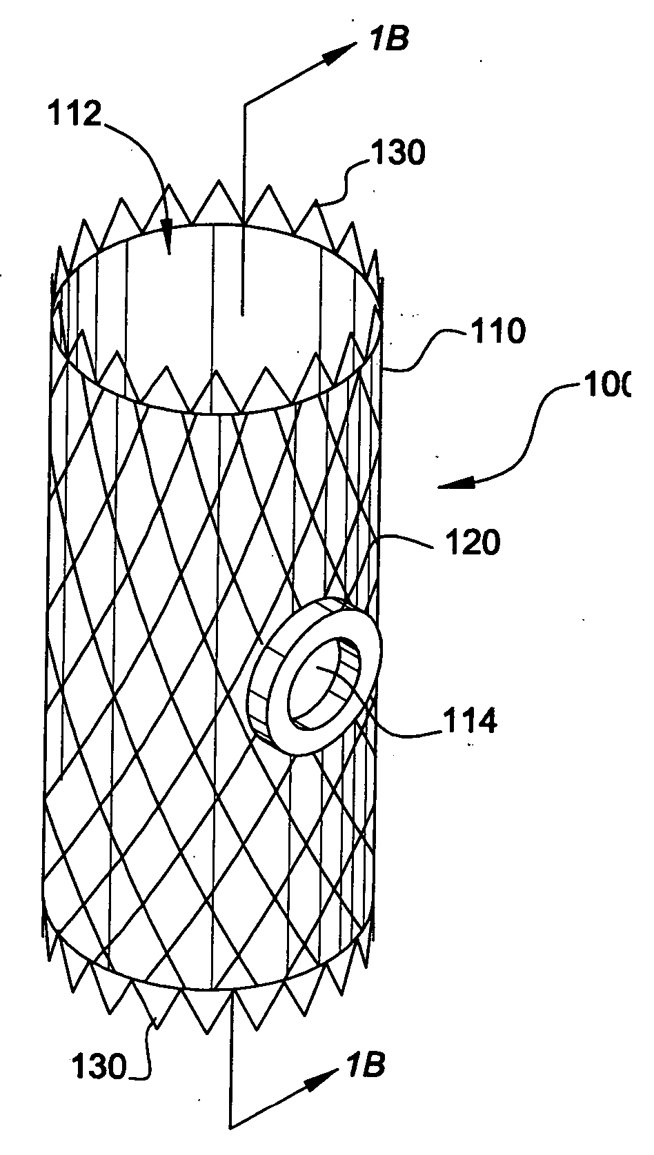
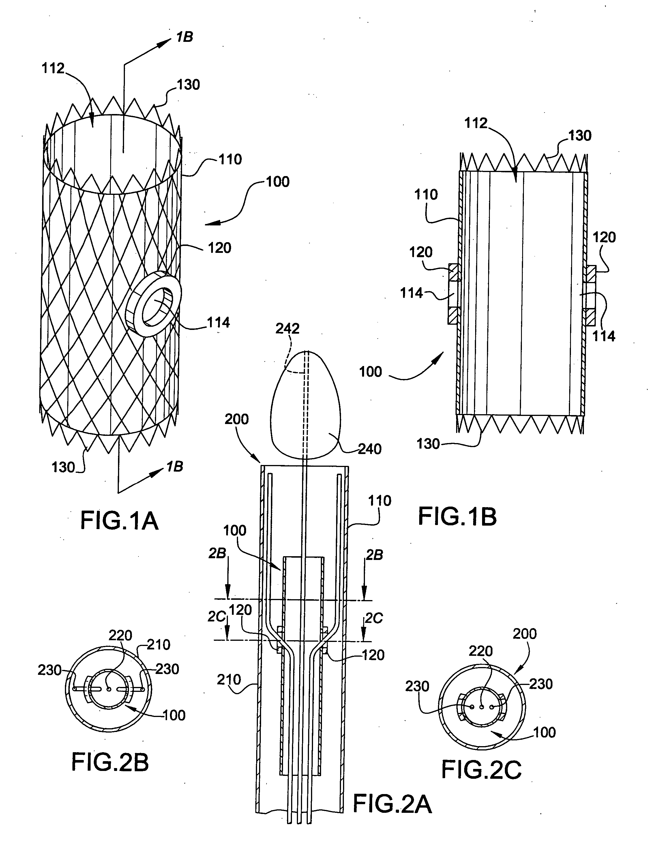
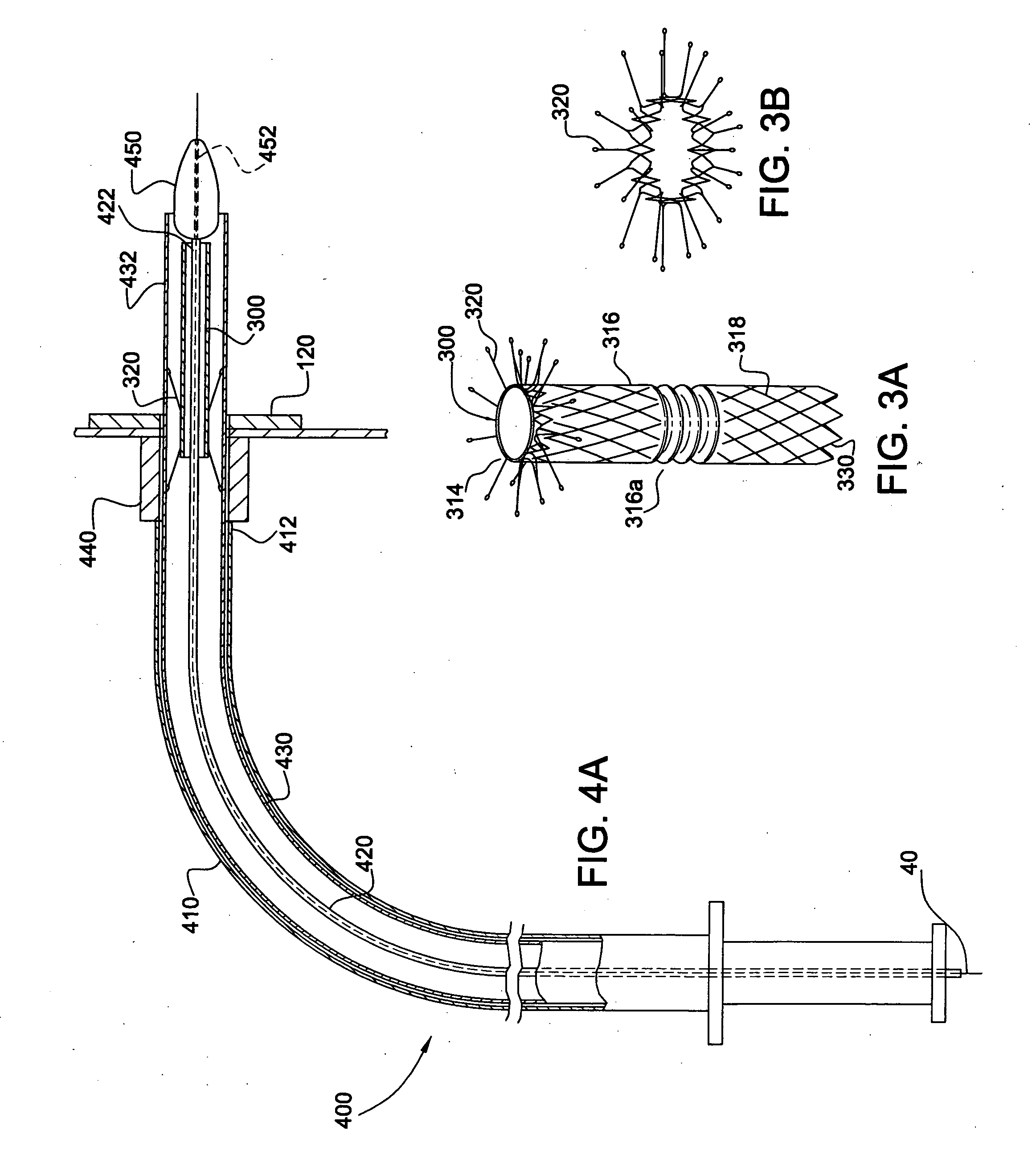
[0066] In accordance with the present invention, the endoluminal grafting system 50 comprises an endoaortic graft 100 (also referred to herein as an “endoaortic cuff”) (FIGS. 1A-1B), an endoaortic graft delivery system 200 for introducing the endoaortic graft 100 into a native, main anatomic conduit 10 (FIGS. 2A-2C), a branch graft 300 (FIG. 3), and a branch graft delivery system 400 for housing the branch graft 300 and introducing it into a branch anatomic conduit 20 extending from the main anatomic conduit 10 (FIGS. 4A-4B).

[0067] As shown in FIGS. 1A-1B, the endoaortic graft 100 comprises a first pliable tube (i.e., a tube formed of a pliable material) having a lumen 112 extending longitudinally therethrough; at least one branch opening 114 (e.g., an aperture) formed in the first pliable tube 110; a flexible magnetic ring 120 incorporated around the at least one branch opening 114 of the first pliable tube 110; and an endoaortic graft anchoring device 130 for holding the first pli...

second embodiment

[0083] In accordance with the present invention, the endoluminal grafting system 50′ comprises an endoaortic graft 100′ (FIGS. 5A-5D), an endoaortic graft delivery system 200 for introducing the endoaortic graft 100′ into a native, main anatomic conduit 10 (FIGS. 2A-2C), a branch graft 300′ (FIGS. 7A-7B), and a branch graft delivery system 400 for housing the branch graft 300′ and introducing it into a branch anatomic conduit 20 extending from the main anatomic conduit 10 (FIGS. 4A-4B).

[0084] As shown in FIGS. 5A-5D, the endoaortic graft 100′ comprises a first pliable tube 110 (i.e., a tube formed of a pliable material) having a lumen 112 extending longitudinally therethrough; at least one branch opening 114 (e.g., an aperture) formed in the first pliable tube 110; a flexible magnetic ring 120 incorporated around the at least one branch opening 114 of the first pliable tube; a coupling mechanism 150 for coupling the branch graft 300′ to the flexible magnetic ring 120; and an endoaor...

third embodiment

[0094] In the invention, the means 460 for maintaining the branch graft 300 in a contracted position includes a deployment wire 462 radially positioned between the inner and middle sheaths 420 and 430, and a thread 464 wrapped around both the contracted branch graft 300 and the deployment wire 462. The thread 464 is made of a biodegradable, absorbable material (for example, PTF or synthetic, absorbable suture sold under the trademarks Vicryl® and Monocryl®). One end 464a of the thread 464 is left as a tail extending at least the length of the outer sheath 412 and the other end (not shown) is secured on itself, for example by a half-knot, to prevent the wrapping from unraveling. The thread 464 is wrapped about the deployment wire 462 and the branch graft 300 in a figure-eight configuration, so that when the deployment wire 462 is retracted, the wrapping unravels, allowing the branch graft 300 to assume an expanded condition.

[0095] The third embodiment of the invention, in which the b...


PUM


Abstract

A system and method for endoluminal grafting of a main anatomic conduit in its diseased state in which it dilates to pose a life threatening condition and its various conduits that emanate from the main anatomic conduit. The grafting system comprises an endoaortic graft having at least one opening therein and at least one branch graft that is passable through the opening of the endoaortic graft into the branch anatomic conduit(s) such that the junction between the branch graft and the endoaortic graft is substantially fluid tight. A system and method for delivery of the endoaortic graft and also a system and method for efficient alignment and deployment of the branch (e.g., side branch) graft such that the coupling of the branch graft with the endoaortic graft is efficient and exact and fluid-tight; and a system and method for coupling the branch to the endoaortic graft via a coupling mechanism employing a memory metal alloy; a system and method for the proper and exact alignment of the endoaortic graft and the branch using magnetic force of a suitable nature, and which does not use the magnetic force as the coupling mechanism.

Description

CROSS-REFERENCE TO RELATED APPLICATIONS [0001] The present patent application is based on, and claims priority from, U.S. provisional Application No. 60 / 509,904, filed Oct. 10, 2003, which is incorporated herein by reference in its entirety.BACKGROUND OF THE INVENTION [0002] 1. Field of the Invention [0003] The present invention relates generally to medical devices and methods, and more particularly to a system and method for endoluminal grafting of blood vessels or other tubular, main anatomic conduits which have furcations or side branches extending there from. [0004] 2. Related Art [0005] Endoluminal grafting is a relatively noninvasive method for placing a tubular graft within the lumen of a native, main anatomic conduit, such as a blood vessel. In certain cardiovascular applications of conventional or prior art techniques for endoluminal grafting, an endovascular graft may be implanted in the aneurismal segment of a blood vessel to form a prosthetic blood flow conduit through t...

Claims


Application Information

Patent Timeline
IPC IPC(8): A61FA61F2/00A61F2/02A61F2/06
CPCA61F2/064A61F2/07A61F2/954A61F2002/061A61F2002/9511A61F2210/009A61F2230/005A61F2250/0069A61F2/90A61F2002/075A61F2220/005A61F2220/0066A61F2220/0075A61F2250/0001
Inventor QUADRI, ARSHAD
Owner CARDIAQ VALVE TECH
Why Eureka
Try Eureka