Laser machining method and laser machining apparatus

a laser machining and laser machining technology, applied in the direction of manufacturing tools, welding/soldering/cutting articles, instruments, etc., can solve the problems of copper conductor layer at the hole bottom being injured, crystal damage, and affecting the accuracy of the hole position, so as to improve the hole quality and the effect of improving the hole position accuracy

Inactive Publication Date: 2005-07-21
HITACHI SEIKO LTD
View PDF9 Cites 37 Cited by
  • Summary
  • Abstract
  • Description
  • Claims
  • Application Information

AI Technical Summary

Benefits of technology

[0035] According to the present invention, the waveform of the laser beam outputted as short pulses is shaped, and the shaped laser beam is supplied to a portion to be machined. Accordingly, laser machining superior in hole position accuracy and hole quality can be performed.

Problems solved by technology

When the pulse repetition frequency is low, there is a fear that the crystal is damaged.
However, the peak intensity is so high that the crystal is apt to be damaged.
In addition, when the remaining amount of the insulating layer is reduced due to the progress of machining, the copper conductor layer at the hole bottom is injured.
(3) When the energy density and the output density are too high in the case where the resin is machined, the copper conductor layer at the hole bottom is injured.
When machining is performed near the maximum output, the hole quality or the hole shape deteriorates.
As a result, the hole position accuracy or the hole shape will deteriorate.
As a result, the hole position accuracy deteriorated up to about 5 μm.
In addition, the hole quality and the hole shape deteriorated due to a fluctuation in output and a broken beam mode (spatial energy distribution).
Further, since conditions suitable for each material cannot be secured, desired hole position accuracy, desired hole quality and desired hole shape could not be obtained.

Method used


Image

  • Laser machining method and laser machining apparatus
  • Laser machining method and laser machining apparatus
  • Laser machining method and laser machining apparatus

Examples


first embodiment

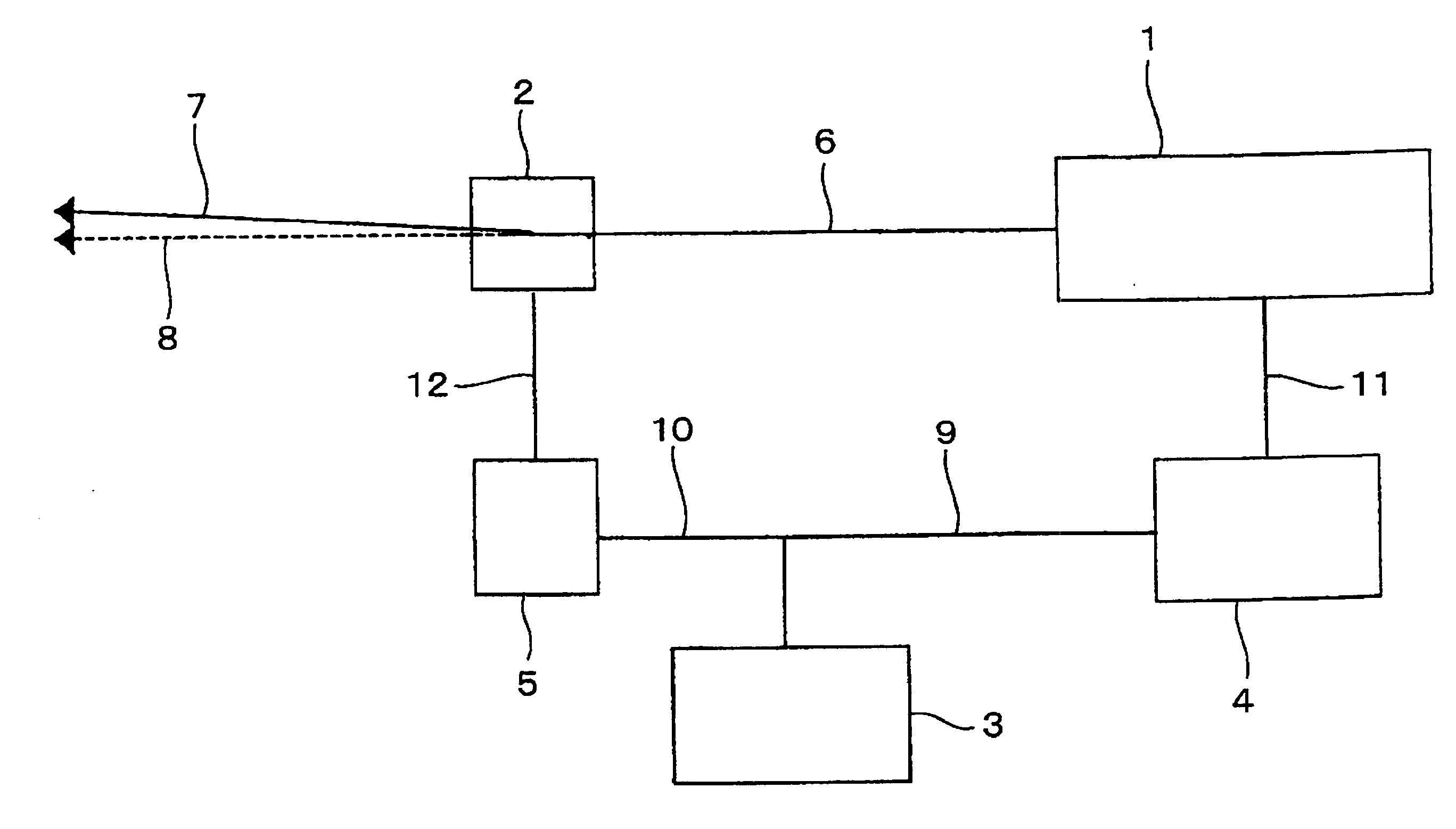
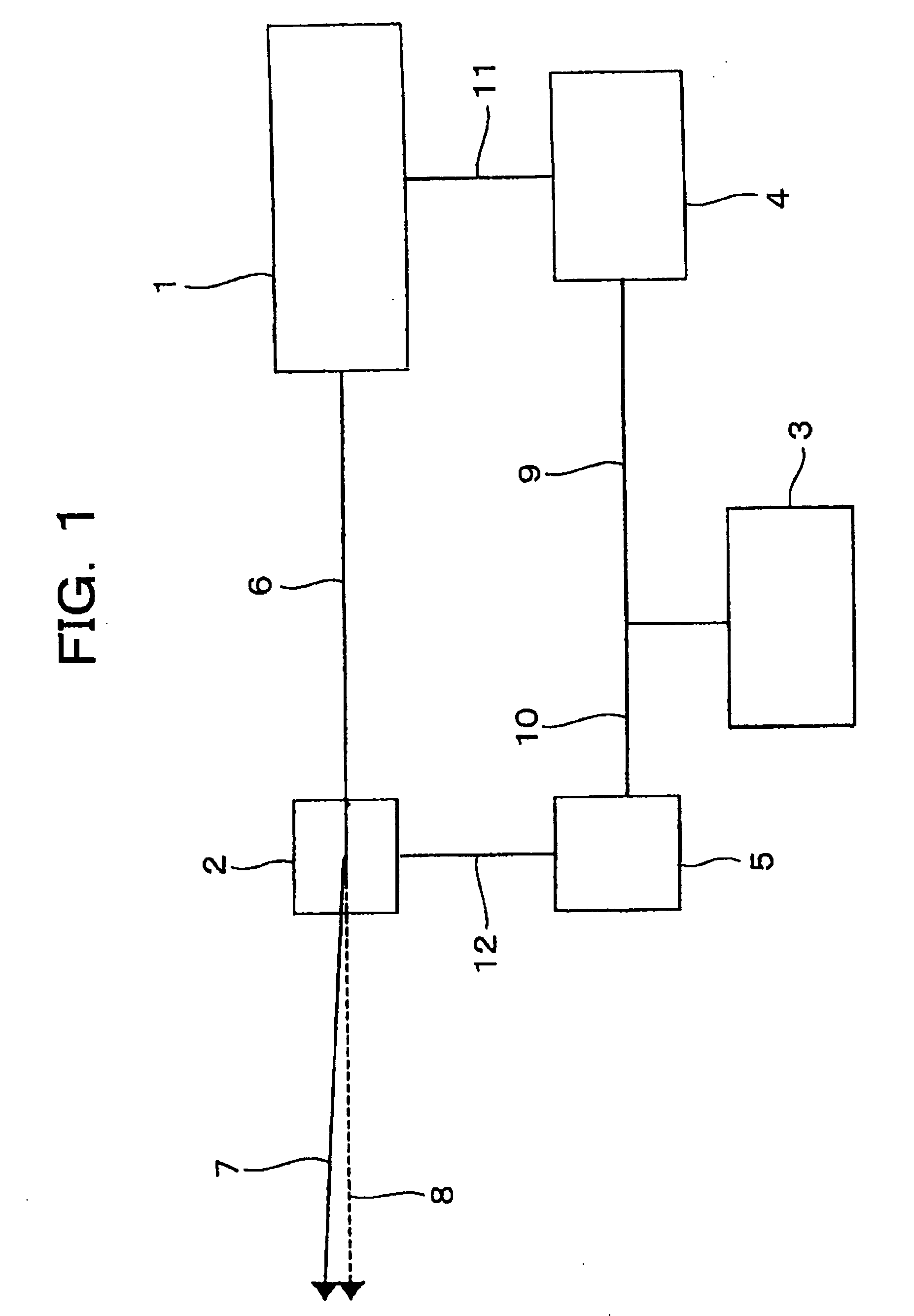
[0048]FIG. 1 is a configuration diagram of a laser machining apparatus according to a first embodiment of the present invention.

[0049] A laser oscillator 1 for outputting a YAG UV laser beam is connected to a system controller 3 through a laser power supply controller 4. A pulse shaper 2 disposed on the optical axis of an outgoing beam 6 outputted from the laser oscillator 1 is connected to the system controller 3 through a pulse shaper controller 5. A #1 branch beam 7 (machining beam) is guided to a not-shown portion to be machined, while a #0 branch beam 8 is guided to a not-shown damper so as to be converted into heat. The laser power supply controller 4 outputs an on / off signal 11 for a Q-SW disposed inside the laser oscillator 1, based on a pulse output instruction signal 9 defining the pulse mode (pulse width, that is, frequency and peak output) of the outgoing beam 6. The pulse output instruction signal 9 is outputted from the system controller 3.

[0050] The pulse shaper con...

second embodiment

[0070]FIG. 6 is a configuration diagram of a laser machining apparatus according to a second embodiment of the present invention. Parts or functions the same as those in FIG. 1 in the first embodiment are referenced correspondingly, and redundant description thereof will be omitted.

[0071] An optical sensor 22 is connected to a pulse shaper controller 5. When reflected light 21 reflected by the surface of a pulse shaper 2 is detected, a detection signal 10a is outputted to the pulse shaper controller 5. The working speed of the optical sensor 22 is about several nanometers.

[0072] In this embodiment, a system controller 3 issues a pulse mode signal 23, that is, an on-time T2 of the pulse shaper 2 to the pulse shaper controller 5.

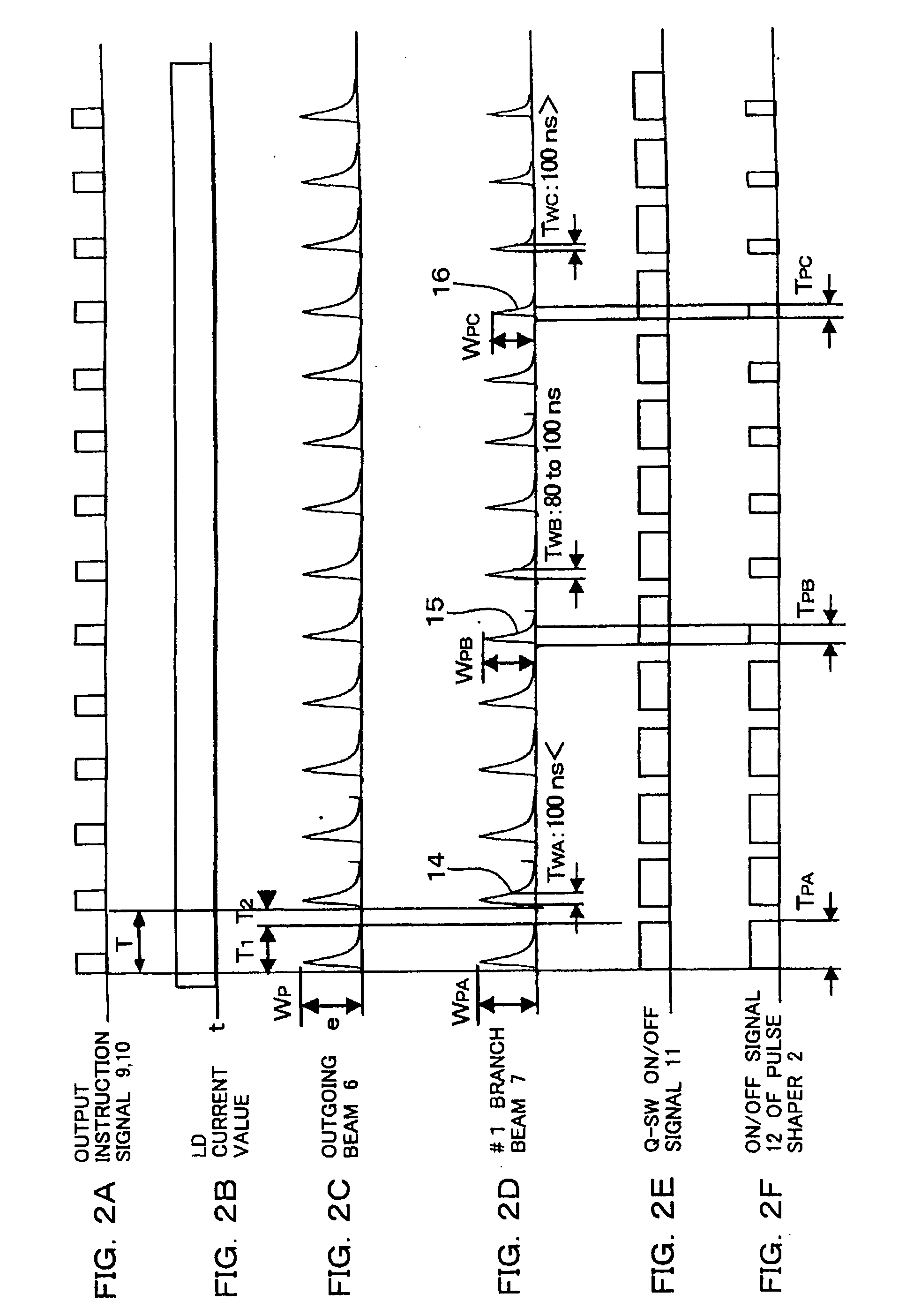
[0073]FIGS. 7A-7G are time charts showing the operation of this embodiment. FIG. 7A shows a pulse output instruction signal 9 and an output instruction signal 23, FIG. 7B shows a value of a current supplied to an LD inside a laser oscillator 1, FIG. 7C show...


PUM

PropertyMeasurementUnit
wavelengthaaaaaaaaaa
diameteraaaaaaaaaa
frequencyaaaaaaaaaa

Abstract

A laser machining method and a laser machining apparatus superior in hole position accuracy and hole quality. An outgoing beam outputted as short pulses is shaped by a pulse shaping unit so as to form a #1 branch beam. The #1 branch beam is supplied to a portion to be machined, so as to machine the portion. In this case, the #1 branch beam may be controlled to synchronize with the outgoing beam. When a piece to be machined is made from a metal material and at least one of an organic material and an inorganic material, the metal material is machined with a laser beam shaped to have a pulse width not shorter than 100 ns, and at least one of the organic material and the inorganic material is machined with a laser beam shaped to have a pulse width shorter than 100 ns.

Description

FIELD OF THE INVENTION [0001] The present invention relates to a laser machining method and a laser machining apparatus suitable for machining printed circuit boards or semiconductor devices. BACKGROUND ART OF THE INVENTION [0002] Pulse energy of a UV laser depends on its emission duration and its excitation duration. Accordingly, higher pulse energy can be generally obtained as the pulse repetition frequency is lower, while the pulse energy becomes lower as the pulse repetition frequency increases. [0003] The peak output and the pulse width depend on the pulse repetition frequency, the kind and the length of the crystal generating the fundamental wave, and the LD (laser diode) output exciting the crystal. Accordingly, the higher the pulse repetition frequency is, the longer the emission duration (that is, the pulse width) is. When the pulse repetition frequency is low, there is a fear that the crystal is damaged. Therefore, the crystal is protected to generate no wave in the low fr...

Claims


Application Information

Patent Timeline
Patent Type & Authority Applications(United States)
IPC IPC(8): B23K26/06B23K26/073B23K26/382B23K101/40B23K101/42H05K3/00
CPCB23K26/04B23K26/063H05K3/0038B23K2201/42B23K2203/12B23K26/383B23K26/0622B23K26/384B23K2101/42B23K2103/12B23K2103/56
Inventor ARAI, KUNIOISHII, KAZUHISAASHIZAWA, HIROAKI
Owner HITACHI SEIKO LTD
Why Eureka
Try Eureka