
Optical filter and display using the same

a technology of optical filter and display screen, applied in the field of optical filter, can solve the problems of lowering in a near infrared shielding property, affecting the performance of various equipment, and often adversely affecting other devices or human bodies or animals, etc., and achieves the effect of increasing haze and lowering transparency

Inactive Publication Date: 2005-07-28
DAI NIPPON PRINTING CO LTD
View PDF7 Cites 33 Cited by
  • Summary
  • Abstract
  • Description
  • Claims
  • Application Information

AI Technical Summary

Benefits of technology

[0008] An object of the present invention is to provide an optical filter which, when disposed on the front face of a display, does not cause image quality problems such as the occurrence of a double image. Another object of the present invention is to provide an optical filter which, under high temperature or humid conditions, does not cause problems such as deteriorated near infrared shielding properties, the appearance of particular absorption in a visible region, coloring or discoloration of images, or a lowering in transparency due to the occurrence of cracks (an increase in haze). Still another object of the present invention is to provide an optical filter with various functions added while solving the above problems. A further object of the present invention is to provide a display, particularly a plasma display, to which these optical filters have been applied.

Problems solved by technology

Electromagnetic waves generated from electric or electronic devices are said to often adversely affect other devices or human body or animals.
This near infrared radiation is regarded as having a fear of causing malfunction of various equipment utilizing a near infrared radiation, for example, remote controllers for home electric appliances and communication equipment utilizing a near infrared radiation such as personal computers and cordless telephones or the like.
In all the above prior art techniques, however, when resins constituting a layer containing an absorbing agent are of some type, problems occur including an image quality problem such as a double image upon the disposition of the optical filter on the front face of the display, a lowering in a near infrared shielding property under high-temperature and humid conditions, and the occurrence of colored or discolored images due to the appearance of particular absorption in a visible region.

Method used


Image

  • Optical filter and display using the same
  • Optical filter and display using the same
  • Optical filter and display using the same

Examples


example 1

[0136] An acrylic copolymer resin comprised of tricyclodecyl methacrylate represented by general formula (1), methyl methacrylate, and benzyl methacrylate (tradename: OPTOREZ oz 1330, Tg: 110° C., hydroxyl value: 0 (zero), acid value: 0 (zero), birefringence value: 4 nm, manufactured by Hitachi Chemical Co., Ltd.) was provided as a transparent binder resin. The binder resin was dissolved in methyl ethyl ketone at a solid content ratio of 20% (on a mass basis) to prepare a resin solution. Two near infrared absorptive colorants, that is, a diimmonium near infrared absorptive colorant in which R in general formula (3) represents trifluoromethyl to constitute a counter ion (X−) and R in general formula (2) represents n-butyl (tradename: CIR 1085, manufactured by Japan Carlit Co., Ltd.) (0.2 g / m2), and a phthalocyanine near infrared absorptive colorant (tradename: “YKR 3070,” manufactured by Yamamoto Chemical Inc.) (0.1 g / m2), were added to and thoroughly dispersed in the resin solution ...

example 2

[0137] A near infrared absorptive filter was prepared in the same manner as in Example 1, except that only the diimmonium near infrared absorptive colorant used in Example 1 was used in an amount of 0.2 g / m2 as the near infrared absorptive colorant.

example 3

[0138] A near infrared absorptive filter was prepared in the same manner as in Example 1, except that an acrylic copolymer resin comprised of isobornyl methacrylate represented by general formula (1), methyl methacrylate, and benzyl methacrylate (Tg: 130° C., hydroxyl value: 0 (zero), acid value: 0 (zero), birefringence value: 9 nm) was used as the transparent binder resin.


PUM


Abstract

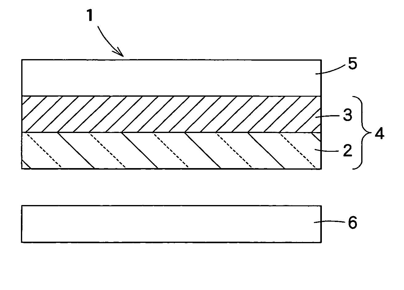
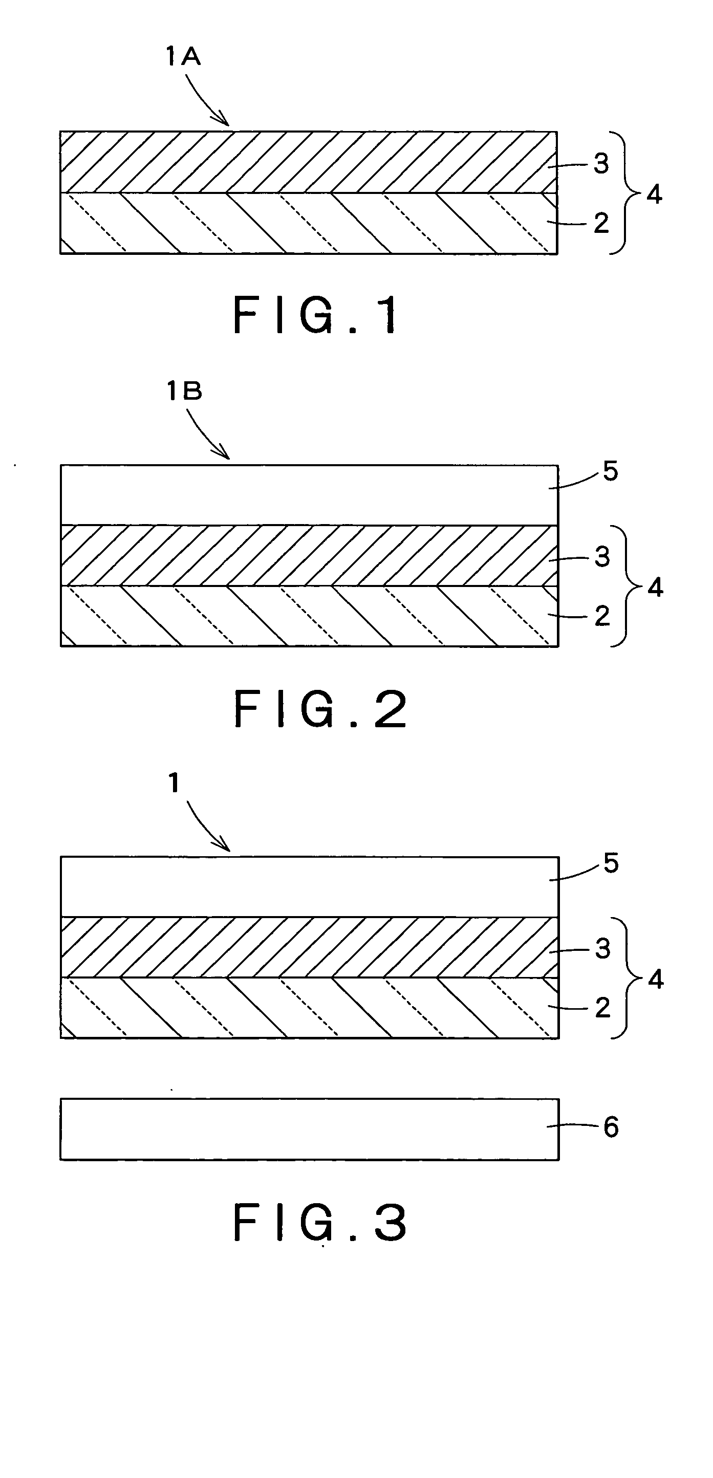
The present invention provides an optical filter possessing excellent near infrared shielding properties. The optical filter has a laminate structure comprising at least a transparent substrate and a near infrared absorptive layer, which is formed of an acrylic resin containing a near infrared absorptive colorant capable of absorbing a near infrared radiation, stacked on top of each other. The acrylic resin has a birefringence value of 0 (zero) to 15 nm.

Description

FIELD OF THE INVENTION [0001] The present invention relates to an optical filter having a near infrared shielding property. The present invention also relates to a display, particularly a plasma display, provided with this optical filter. BACKGROUND ART [0002] Electromagnetic waves generated from electric or electronic devices are said to often adversely affect other devices or human body or animals. For example, electromagnetic waves with a frequency of 30 MHz to 130 MHz are generated from a plasma display (hereinafter often abbreviated to “PDP”) and sometimes affect computers or equipment utilizing computers located around the PDP. Therefore, minimizing leakage of generated electromagnetic waves to the exterior has been desired. [0003] In PDP, since a mixed gas composed of neon and xenon is used as discharge gas, a near infrared radiation with a wavelength of 800 nm to 1200 nm is emitted. This near infrared radiation is regarded as having a fear of causing malfunction of various e...

Claims


Application Information

Patent Timeline
IPC IPC(8): B32B9/00H04N5/65G02B5/20G02B5/22H01J17/49H04N5/72
CPCY10T428/14G02B5/208H04N5/65H04N5/72
Inventor NAKATSUGAWA, YUJI
Owner DAI NIPPON PRINTING CO LTD
Learn More