Magnetic tracking system

a tracking system and magnetic field technology, applied in the field of magnetic tracking systems, can solve the problems of limiting the attainable field strength or the achievable level of detection signal amplitude, introducing distortions into the expected or calibrated field distribution, and varying magnetic fields induce eddy currents in conductive structures found within the field, so as to enhance the accuracy of p&o determination, enhance the accuracy of tracking determination, and moderate or effectively null electromagnetic disturbances

Inactive Publication Date: 2005-07-28
NORTHERN DIGITAL
View PDF35 Cites 37 Cited by
  • Summary
  • Abstract
  • Description
  • Claims
  • Application Information

AI Technical Summary

Benefits of technology

[0020] In accordance with another aspect, an operating room system of the invention may employ a conductive shield, or a sheath structure configured to fit about or contain an interfering component or piece of equipment The sheath standardizes the magnetic field disturbance introduced by the component In some instances the sheath may be a metal cylinder, dimensioned to enclose the disturbing piece of equipment. The sheath or cylinder may be formed of sheet metal of a gauge such that eddy currents are induced by the magnetic field, thus giving rise to a standardized field disturbance originating at a contour or surface external to the equipment. Alternatively, other suitable conductive materials, such as a carbon fiber composite material, may be used. The sheath also moderates or effectively nulls electromagnetic disturbances originating within its contour, e.g., at the underlying piece of equipment disposed within the sheath. The inclusion of this standardized disturbance in a system of the invention permits the interchange of different pieces of equipment without introducin...

Problems solved by technology

Small coils offer the prospect of generating, to a close approximation, dipole fields, although small size may limit the attainable field strength or the achievable level of detection signal amplitude.
While the latter approach offers some processing advantages (such as being able to synchronously demodulate induced signals, and thus cumulate detected signal values to enhance sensitivity, and also the ability to establish the X, Y and Z field components at different frequencies so that detected sensor output signals may be separated or even demodulated simultaneously), it has the disadvantage that varying magnetic fields induce eddy currents in conductive structures found within the field.
Induced currents themselves then generate secondary magnetic fields, thus introducing distortions into the expected or calibrated field distribution.
However, this approach may be unrealistically restrictive for certain applications, including some image guided surgery applications, where highly disturbing equipment (such as the imaging assembly of a fluoroscope) is necessarily placed as close as possible to the work arena in which tracking is to occur.
However, as a practical matter, such mapping is not only likely to require a time-consuming preliminary set-up operation, but may require that the set-up be carried out afresh for each new arrangement of operating room equipment that introduces different di...

Method used


Image

  • Magnetic tracking system
  • Magnetic tracking system
  • Magnetic tracking system

Examples


Embodiment Construction

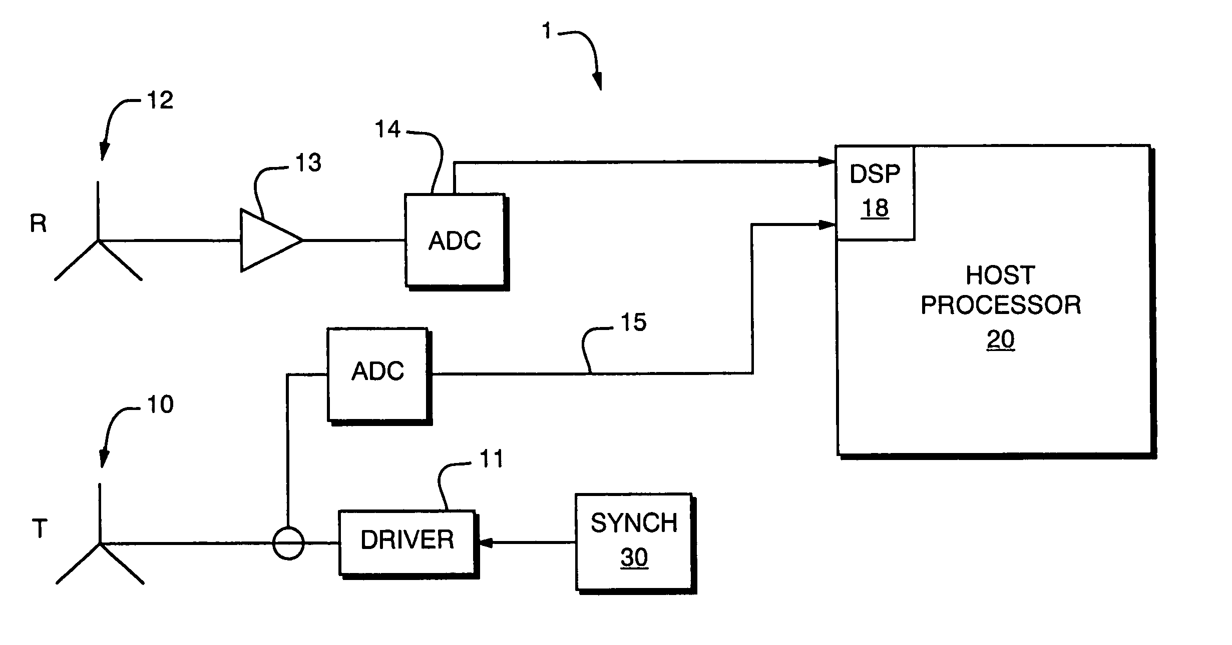
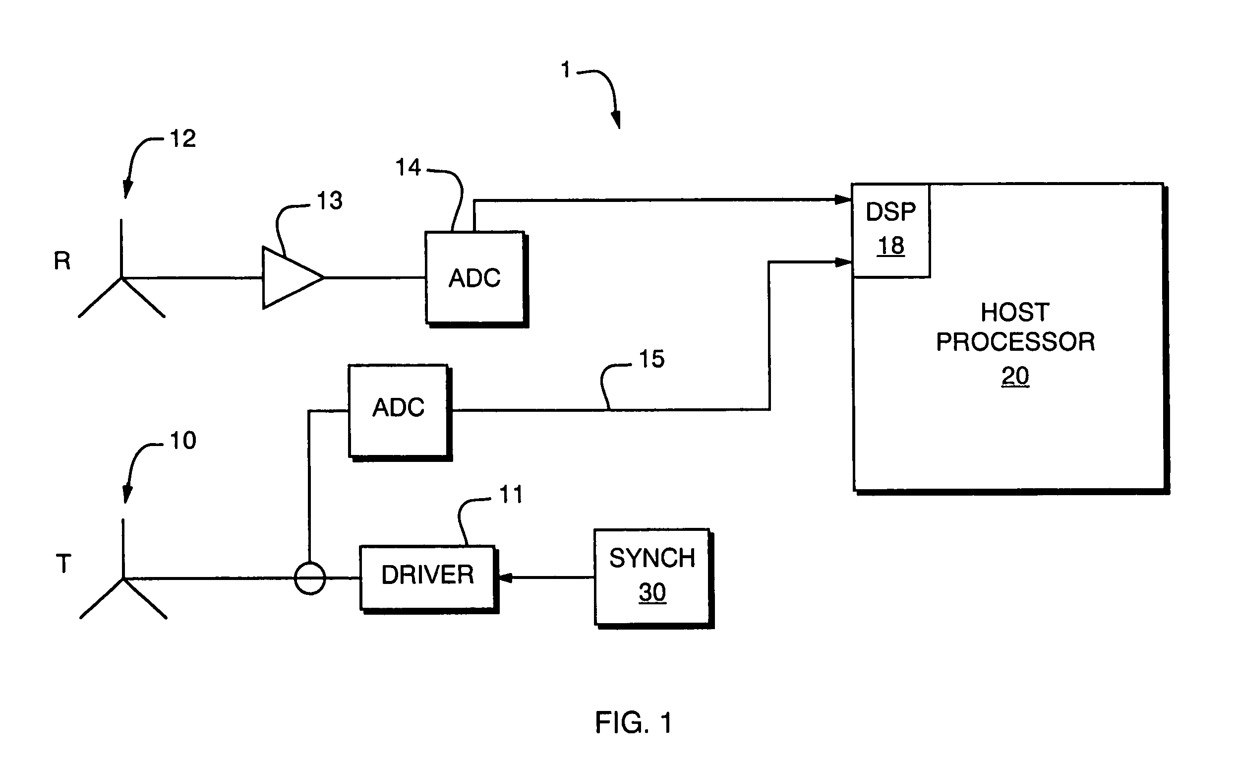
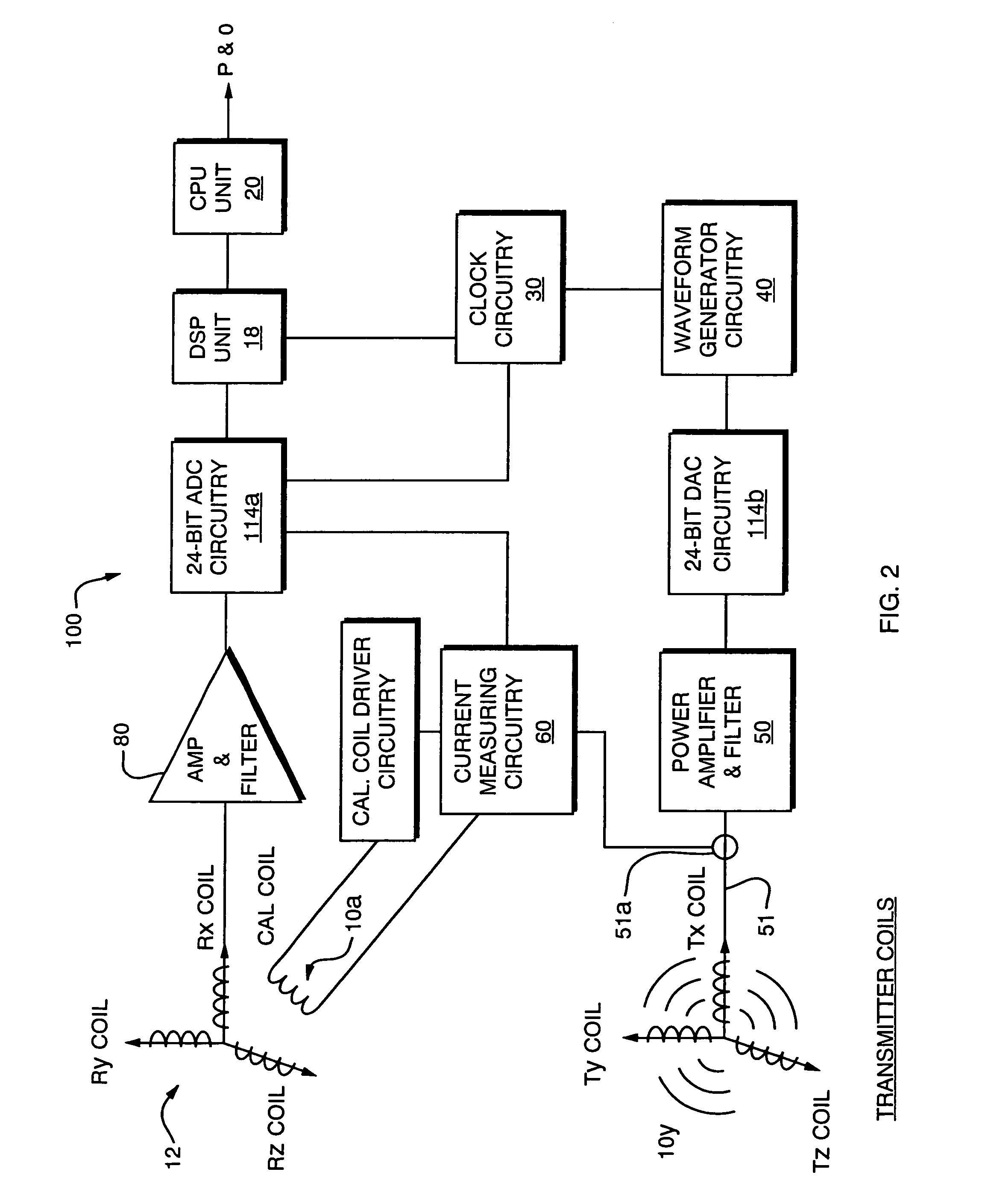
[0031] The present invention is an improved electromagnetic tracking system which may, by way of example, be employed in an operating room or clinical setting to determine the position and orientation of an object such as a catheter, surgical tool, marker or the like in relation to other physical structures, or in relation to images that may, for example, have coordinates assigned thereto by other means, such as via coordinatized 3-D image sets, position-defining frames, or correlation with imaged or tracked fiducials or markers. A great number of such systems are known, being described for example in U.S. Pat. No. 5,967,980 and related patents of M. Ferre et al, No. 5,307,072, and others, so the features of such systems will not be further described here.

[0032] As relevant to a first aspect of the present invention, an electromagnetic tracking system includes a magnetic field generator and a magnetic field sensor together with signal conditioning circuitry and a processor for proc...


PUM


Abstract

The present invention provides an electromagnetic tracking system that includes a field generator and a field sensor arranged to generate and detect, respectively, an electromagnetic field. Both the transmitter and receiver coils are connected to signal conditioning and processing circuitry to provide outputs indicative of the coil signals. A processor operates on the signals to determine the coordinates of the sensing assembly relative to the generator assembly. The signal processor produces ratiometric outputs, and applies a mutual inductance model to solve for position/orientation coordinates. In some embodiments, a disturber in the form of a conductive ring or a sheath is disposed about an interfering piece of equipment to moderate and standardize disturbances due to eddy currents.

Description

BACKGROUND OF THE INVENTION [0001] The present invention relates to magnetic tracking systems of the type wherein a magnetic field is established in a relevant work area, and one Or more magnetic field sensors are operated to sense values of a local magnetic field and are processed to determine the position of a tool, instrument or other identified object. In general, such systems operate using a field generating element or assembly, and a field sensing element or assembly, often in conjunction with other position determining elements, such as robotic stepper or optical tracker assemblies to track the relative changes in position between one or more fixed points or structures in the physical environment or associated images, and one or more moving or non-visible points or structures in the work arena. [0002] Magnetic field generating or sensing assemblies for tracking may be implemented in various ways, with conventional analog wire coils forming current loops or paths, or with semi...

Claims


Application Information

Patent Timeline
IPC IPC(8): A61B19/00
CPCA61B5/06A61B19/52A61B19/5244A61B2019/502A61B2019/5458A61B2019/5251A61B2019/5255A61B2019/5268A61B2019/5272A61B2019/5238A61B2034/102A61B90/36A61B2034/2055A61B2034/2068A61B2034/2072A61B34/20A61B2090/376A61B2034/2051A61B2090/3958
Inventor ANDERSON, PETER T.BEAUREGARD, GERALD L.CHERRY, CHRISTOPHER D.
Owner NORTHERN DIGITAL
Why Eureka
Try Eureka