
System for electromagnetic radiation dermatology and head for use therewith

a dermatology and electromagnetic radiation technology, applied in the field of electromagnetic radiation, can solve the problems of increasing the energy absorption of the epidermis, the potential for damage to the epidermis, and the energy which can be used, and achieve the effects of facilitating larger spots, enhancing patient satisfaction and practitioner profitability, and reducing the risk of skin damag

Inactive Publication Date: 2005-08-04
PALOMAR MEDICAL TECH
View PDF13 Cites 40 Cited by
  • Summary
  • Abstract
  • Description
  • Claims
  • Application Information

AI Technical Summary

Benefits of technology

"This patent describes a system and head for treating dermatological problems by using EM radiation. The system includes an optical waveguide and a mechanism for cooling the patient's skin. The head has a sensor to measure the temperature at the patient's DE junction (the area where the waveguide makes contact with the skin). The sensor is located at the second end of the waveguide. The system also includes a mechanism for removing heat from the waveguide. The invention also includes a standoff with a reflective surface to return back-scattered radiation to the patient's skin. The standoff creates negative pressure in the chamber where the patient's skin is in contact with the waveguide, ensuring good thermal contact. The technical effects of this invention include improved treatment efficacy and better control over the treatment area."

Problems solved by technology

One problem with such treatments is that the only way to get the radiation to a target volume in the dermis where treatment is desired is to transmit the radiation to such volume through the overlying epidermis.
However, as the energy applied through the epidermis increases, the potential for damage to the epidermis as a result of energy absorption therein also increases.
Therefore, one limitation on the energies which can be used for various dermatological treatments in the dermis, and in particular on the depths in the dermis at which treatment can be performed, and on the size of the elements which can be treated, is that the energy applied cannot be so high as to cause appreciable damage to the epidermis.
However, these prior art systems have not been wholly satisfactory.
However, it is not desirable that the cooling extend significantly below the DE junction into the dermal layer since cooling in the dermal layer can potentially inhibit the desired thermal damage to follicles, blood vessels or the like in this region.
Further, there are significant variations in radiation absorption by a patients skin, not only among different individuals, people having darker skin absorbing more radiation and being more prone to epidermal damage than people with lighter skin, but even for different areas on the body of a single individual.
Therefore, cooling which is not customized to the treatment area generally results in the cooling not being to the proper depth, a problem which can interfere with treatment and / or permit thermal damage to the epidermis.
However, while infrared sensors have for example been utilized in the past to detect temperature at the surface of the skin, such detection does not provide an accurate indication of temperature even at the skin surface, these readings varying with such factors as skin layer thickness, skin roughness and skin color in addition to temperature.
However, differences in skin thickness and elasticity, differences in bone backing and other factors affect the pressure required to achieve good thermal contact for different patients and for different areas on the body for the same patient.
This is another reason why highly trained and skilled individuals are required for performing the treatments and contributes to the high cost of the treatment.
Related but opposite problems arise in performing certain skin resurfacing / wrinkle removal procedures where the objective is to heat and destroy only the most surface layer of the skin, for example the epidermis, with minimal damage to underlying layers.
However, variations in patient's skin make such tight control difficult even for highly trained and skilled personnel.
Similar problems also arise in other dermatological procedures involving lasers or other radiation sources.
Another related problem in using an EM radiation source for dermatological treatment is that the skin reflects back a significant portion of the radiation applied thereto.
However, existing retro-reflector devices have not optimized the collection and return of such back-scattered radiation and improved techniques for the more efficient reutilization of back-scattered radiation is therefore desirable.
One particular problem with prior art retroreflectors is that they reflect all back-scattered radiation at substantially the same angle the radiation was received; however, radiation at an angle more parallel than perpendicular to the skin surface generally does not reach the treatment area and therefore only heats the surface of the skin, contributing to thermal damage of the skin, without having any beneficial / therapeutic effect.
Spot size is typically limited by the optics of the handpiece utilized and by the desired fluence as a function of the available energy source.
Secondly, anything which reduces the distance from the irradiation source to the target area reduces the amount of energy required to achieve a desired therapeutic effect and anything which permits more of the applied energy to reach the target area has a similar effect.

Method used


Image

  • System for electromagnetic radiation dermatology and head for use therewith
  • System for electromagnetic radiation dermatology and head for use therewith
  • System for electromagnetic radiation dermatology and head for use therewith

Examples


Embodiment Construction

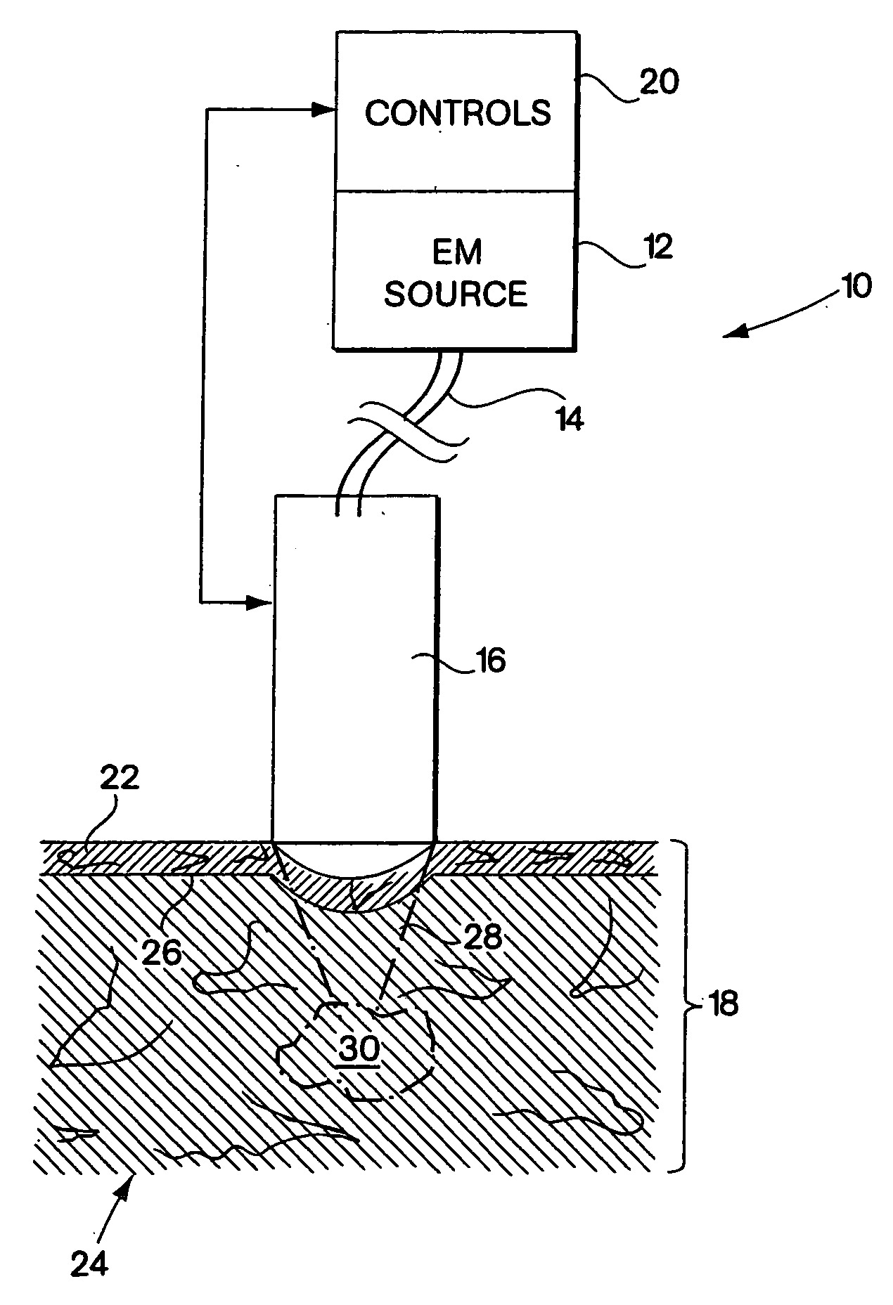
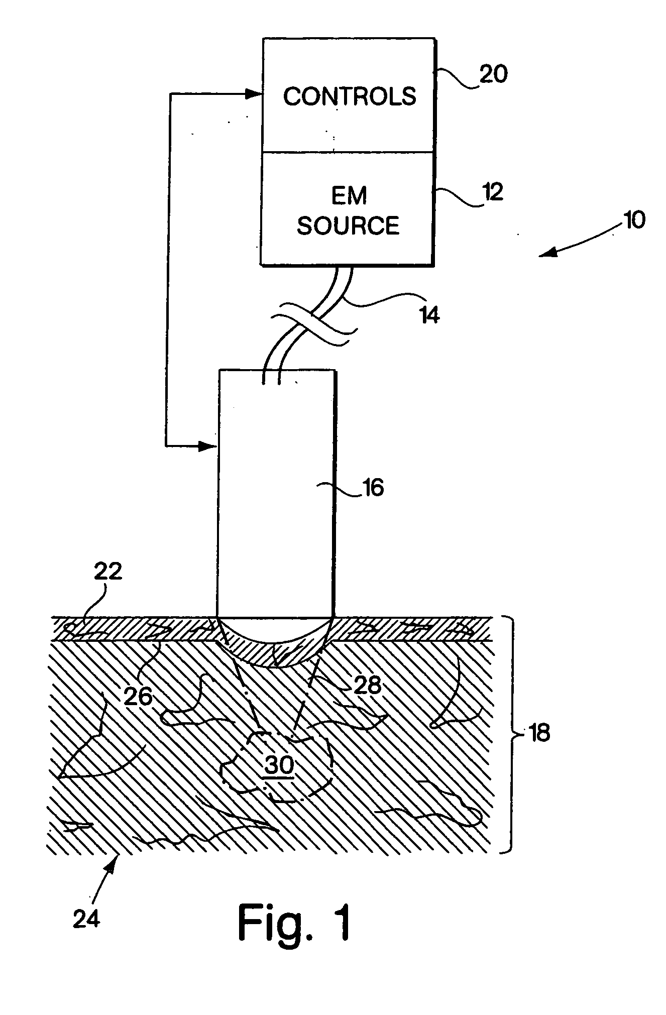
[0030]FIG. 1 is a simplified block diagram of a system 10 which may be utilized for treating a selected dermatological condition in accordance with the teachings of this invention. The system includes an electromagnetic (EM) radiation source 12 which is connected through a fiber optic light pipe or other suitable optical conveyor 14 to an applicator or head 16, which head is in contact with the skin 18 of a patient. Controls 20 are provided which receive information from source 12 and head 16 and which control operation of the system in response to these inputs and others. EM source 12 may be a ruby laser, alexandrite laser, diode laser or other laser source providing radiation of a suitable wavelength for the laser treatment to be performed, or may be a lamp or other non-coherent electromagnetic radiation source providing signals at the requisite wavelength. Particularly for non-coherent light sources, various techniques may be utilized to filter, frequency shift or otherwise contr...


PUM


Abstract

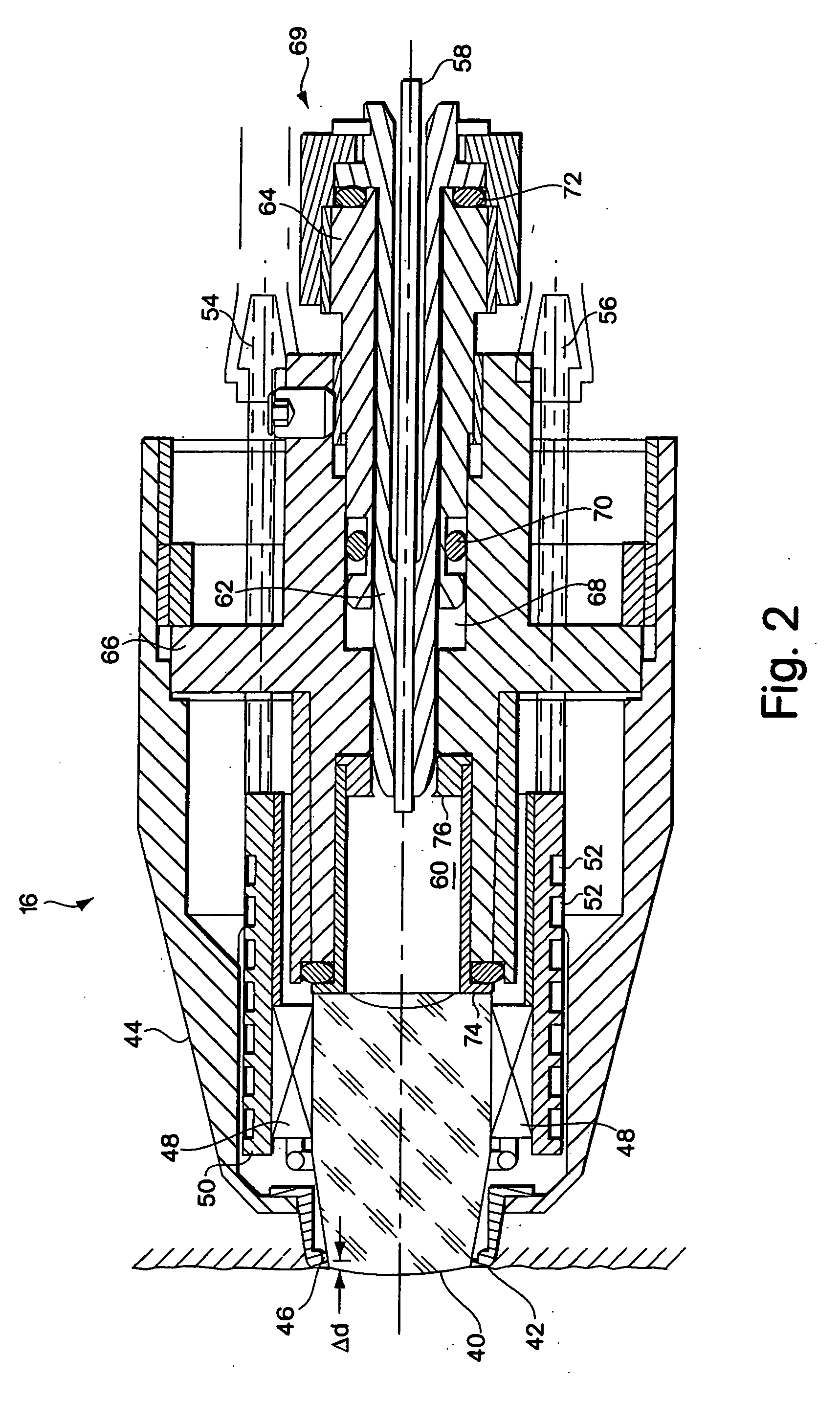
A system for treating a selected dermatological problem and a head for use with such system are provided. The head may include an optical waveguide having a first end to which EM radiation appropriate for treating the condition is applied. The waveguide also has a skin-contacting second end opposite the first end, a temperature sensor being located within a few millimeters, and preferably within 1 to 2 millimeters, of the second end of the waveguide. A temperature sensor may be similarly located in other skin contacting portions of the head. A mechanism is preferably also provided for removing heat from the waveguide and, for preferred embodiments, the second end of the head which is in contact with the skin has a reflection aperture which is substantially as great as the radiation back-scatter aperture from the patient's skin. Such aperture may be the aperture at the second end of the waveguide or a reflection plate or surface of appropriate size may surround the waveguide or other light path at its second end. The portion of the back-scattered radiation entering the waveguide is substantially internally reflected therein, with a reflector being provided, preferably at the first end of the waveguide, for returning back-scattered light to the patient's skin. The reflector may be angle dependent so as to more strongly reflect back scattered light more perpendicular to the skin surface than back scattered radiation more parallel to the skin surface. Controls are also provided responsive to the temperature sensing for determining temperature at a predetermined depth in the patient's skin, for example at the DE junction, and for utilizing this information to detect good thermal contact between the head and the patient's skin and to otherwise control treatment. The head may also have a mechanism for forming a reflecting chamber under the waveguide and drawing a fold of skin therein, and for providing a second enlarged waveguide to expand the optical aperture of radiation.

Description

RELATED APPLICATIONS [0001] This application is a continuation of patent application Ser. No. 10 / 245,825, filed Sep. 17, 2002, which is in turn a continuation of patent application Ser. No. 09 / 268,433, filed Mar. 12, 1999, which application claims priority to Provisional Application 60 / 115,447, filed Jan. 8, 1999 and Provisional Application 60 / 077,794, filed Mar. 12, 1998. Said patent application Ser. No. 09 / 268,433 is also a continuation-in-part of patent application Ser. No. 08 / 759,036, filed Dec. 2, 1996, now U.S. Pat. No. 6,015,404; patent application Ser. No. 08 / 759,136, filed Dec. 2, 1996, now abandoned; and patent application Ser. No. 09 / 078,055, filed May 13, 1998, now U.S. Pat. No. 6,273,884, which application claims priority to Provisional Application 60 / 046,542, filed May 15, 1997; and Provisional Application 60 / 077,726, filed Mar. 12, 1998. This application is also a continuation-in-part of patent application Ser. No. 09 / 473,910, filed Dec. 28, 1999, which application cl...

Claims


Application Information

Patent Timeline
Patent Type & Authority Applications(United States)
IPC IPC(8): A61B17/00A61B18/00A61B18/20A61B18/22A61B19/00A61N5/06
CPCA61B18/203A61N5/0617A61B2017/00057A61B2017/00084A61B2017/00106A61B2017/00752A61B2017/00756A61B2017/00769A61B2018/00005A61B2018/00023A61B2018/00041A61B2018/00452A61B2018/00458A61B2018/00476A61B2018/1807A61B2018/2261A61B2019/465A61B18/22A61B2090/065A61B2017/00747
Inventor ALTSHULER, GREGORY B.ZENZIE, HENRY M.
Owner PALOMAR MEDICAL TECH
Learn More