
Microscale sorting cytometer

a micro-scale, cytometer technology, applied in electrostatic separators, diaphragms, electrolysis, etc., can solve the problems of inability to sort subpopulations of observed cells based on morphological or intracellular information, lack of ability to observe cells microscopically and arbitrarily sort subpopulations of observed cells, and inability to understand cell function, etc., to achieve the effect of greater field strength

Inactive Publication Date: 2005-08-11
MASSACHUSETTS INST OF TECH
View PDF6 Cites 104 Cited by
  • Summary
  • Abstract
  • Description
  • Claims
  • Application Information

AI Technical Summary

Benefits of technology

[0018] In another embodiment, an illumination source is operatively positioned to direct radiation to said vessels, which is one embodiment, is a laser. In another embodiment, a beam splitter is employed with the use of said illumination source. In another embodiment, a recording device is operatively positioned to record a parameter in said cytometer. In another embodiment, the recording device is a camera, a computer, a luminometer, a spectrophotometer, or a combination thereof In another embodiment, the deposit and patterning of said dielectically separated crossing electrodes on said array is optimized to produce greater field strength exerted on cells trapped in said vessels.

Problems solved by technology

Although cells exhibit complex intracellular and morphological behavior, and carry out functions over time, limitations in the ability to genetically probe these processes directly hinders the ability to understand cell function.
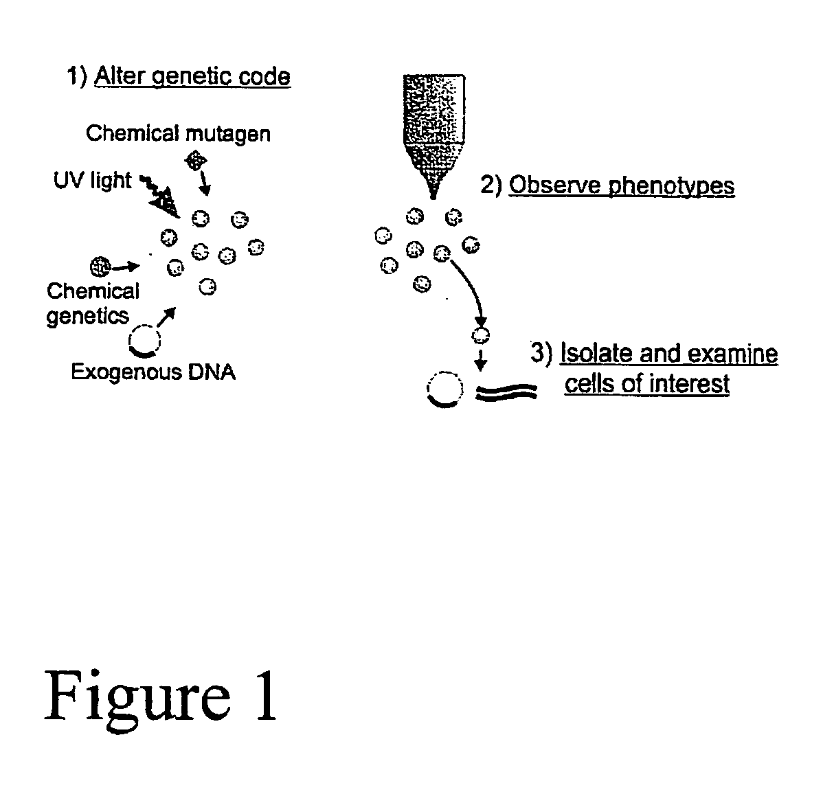
Currently, an ability to observe cells microscopically and then arbitrarily sort subpopulations of the observed cells, on a reasonably large scale, is lacking.
Flow cytometry and the related fluorescence-activated cell sorting (FACS) flow cells in a buffer single-file past an interrogation point, allowing high-throughput (>10,000 cells / sec) analysis of light scatter and whole-cell fluorescence, however, flow sorters do not image, making them unable to sort based upon morphological or intracellular information, and their very nature as flowing systems makes it difficult to observe the same cell at widely spaced timepoints, as would be needed to screen for temporal behavior.
All conventional microscopy technologies, however, are limited in their ability to viably isolate cells following imaging.
Cell-based genetic screens, employing the observation of cells and their isolation when exhibiting a desired phenotype, has been accomplished via the use of microscopy, however, its use is severely limited in its ability to isolate positive-responding cells.

Method used


Image

  • Microscale sorting cytometer
  • Microscale sorting cytometer
  • Microscale sorting cytometer

Examples


example 1

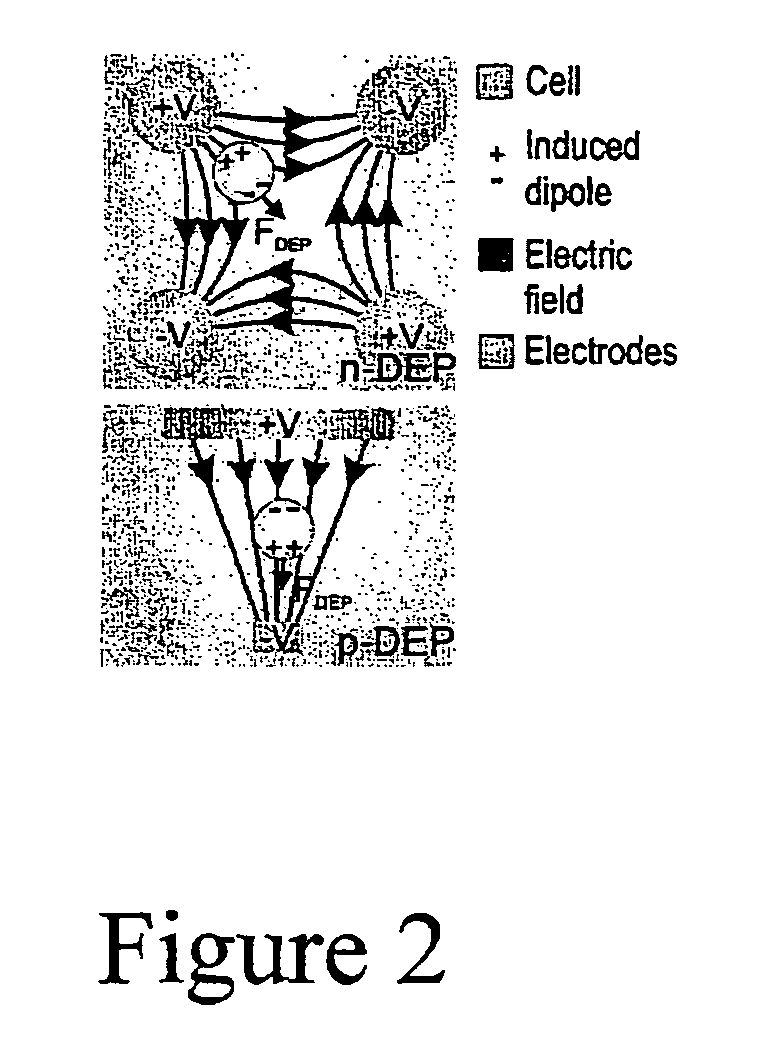
DEP-Based Cellular Trap

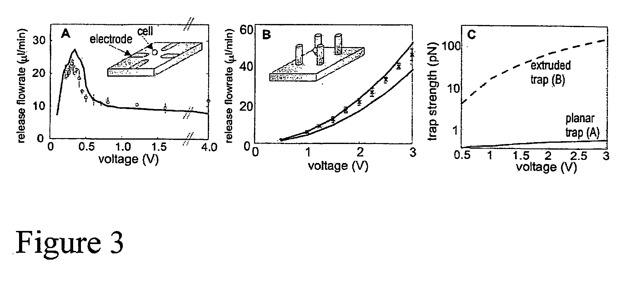
[0117] In order to design a DEP trap that works well enough to be scaled to a large array, unique modeling software for quantitatively designing DEP traps was developed. This software allows one to simulate the performance of an arbitrary three-dimensional trap given the geometry, operating parameters (voltage, frequency, etc.), fluid flow (flow profile, flow rate, etc.), and cell parameters (radius, electrical characteristics). The software took numerically calculated electric fields (FEMlab by COMSOL, Inc.) and imported the data into Matlab. Then, using full dielectrophoretic theory, the multi-polar dielectrophoretic forces exerted on the cell everywhere in space was calculated, which, allowed for the accurate simulation of arbitrarily complex geometries. Other forces may also then be calculated, depending on the situation of interest: gravitational forces, hydrodynamic drag and lift forces, etc. Once all the forces were calculated, the program determined w...

example 2

Functional DEP-Based Sorting Cytometers

[0119] The traps designed in the modeling step of Example 1 were then constructed, and are shown in FIG. 4. These traps were designed for non-adherent mammalian cells (leukocytes). The traps were created on a glass (Pyrex) substrate, and consisted of electroplated gold post electrodes atop a 0.5 mm-thick Ti / Au interconnect layer. The traps were enclosed in a 150-mm high flow chamber with a polymer gasket (made of SU-8 photoresist) that was capped with a coverslip to allow high-fidelity optical access. With this array, capture, holding, and arbitrary sorting of individual HL-60 cells was accomplished. In addition, cultured HL-60 cells, were resuspended in PBS, trapped in the cytometer and then calcein was introduced into the chamber and the cytometer was imaged for 45 minutes, after which cells were sorted.

[0120] Traps that use DEP to independently pattern cells and extracellular matrix were developed as well. As shown in FIG. 5A, traps consis...

example 3

Scalable nDEP-Based Traps

[0121] The design of an n-DEP trap that would be easier to fabricate, amenable to use with adherent cells, robustly trap only single cells, and be able to be operated in a large array format was undertaken. In conjunction with the design, the modeling software was extended in order to predict temperature rises during trapping. FIG. 6 demonstrates another trap geometry, which meets these requirements.

[0122] The trap 28 consists of two electrodes (metal layers 1 (10) and 2 (12)) surrounding a well 14. When energized, the electrodes create a DEP barrier that keeps trapped cells within the trap and untrapped cells out of the trap, thus ensuring robust single-cell trapping. The trap spacing is 59 mm with a 30 mm-wide well, appropriately sized to hold single NIH 3T3 fibroblasts.

[0123] Assembling a cytometer based on such a trap may be as depicted in FIG. 7. Loading of the cells occurs passively, while engagement of the traps via application of voltage, concurre...


PUM

PropertyMeasurementUnit
Electric potential / voltageaaaaaaaaaa
Electric field strengthaaaaaaaaaa

Abstract

The present invention provides a device and methods of use thereof in microscale cell sorting. This invention provides sorting cytometers, which trap individual cells within vessels following exposure to dielectrophoresis, allow for the assaying of trapped cells, such that a population is identified whose isolation is desired, and their isolation.

Description

CROSS-REFERENCE TO RELATED APPLICATIONS [0001] This Application claims priority from United States Provisional Application Serial No. 60 / 539,567, filed Jan. 29, 2004, which is hereby incorporated in its entirety.FIELD OF THE INVENTION [0002] This invention provides devices and methods of use thereof in cell sorting This invention provides a microscale sorting cytometer, which is based on the dielectrophoretic manipulation of individual cells, which can be analyzed and subsequently sorted. BACKGROUND OF THE INVENTION [0003] Systematic investigation and understanding of cells depends on the tools available with which to probe cell function. Although cells exhibit complex intracellular and morphological behavior, and carry out functions over time, limitations in the ability to genetically probe these processes directly hinders the ability to understand cell function. Currently, an ability to observe cells microscopically and then arbitrarily sort subpopulations of the observed cells, o...

Claims


Application Information

Patent Timeline
IPC IPC(8): C12M1/34C12Q1/00G01N15/10G01N15/14
CPCB03C5/005B03C5/026B03C2201/26G01N2015/149G01N2015/0038G01N2015/1006G01N2015/1081G01N15/1475G01N2015/1028G01N15/1433G01N15/149
Inventor VOLDMAN, JOELTAFF, BRIAN MICHAEL
Owner MASSACHUSETTS INST OF TECH
Learn More