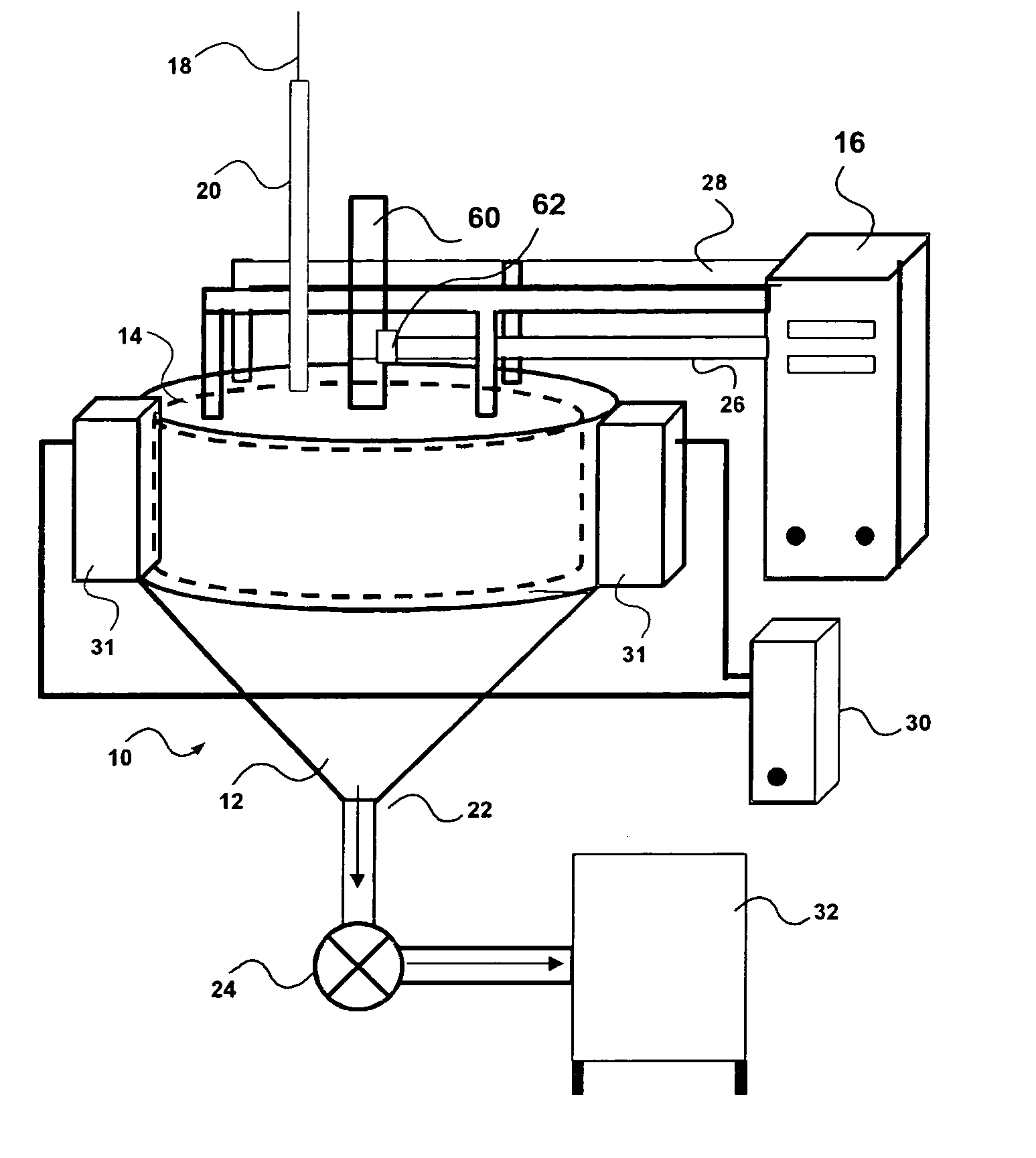
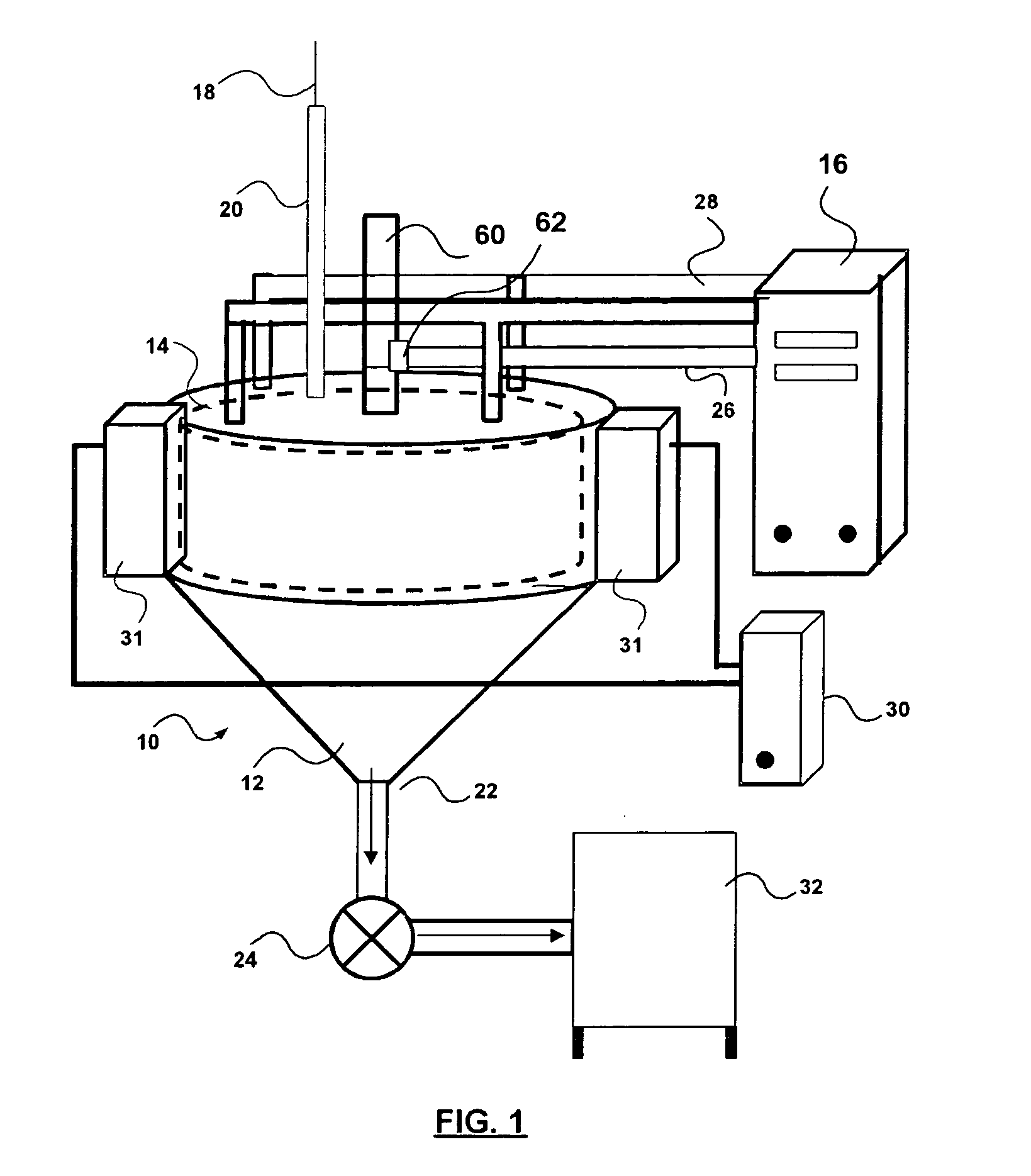
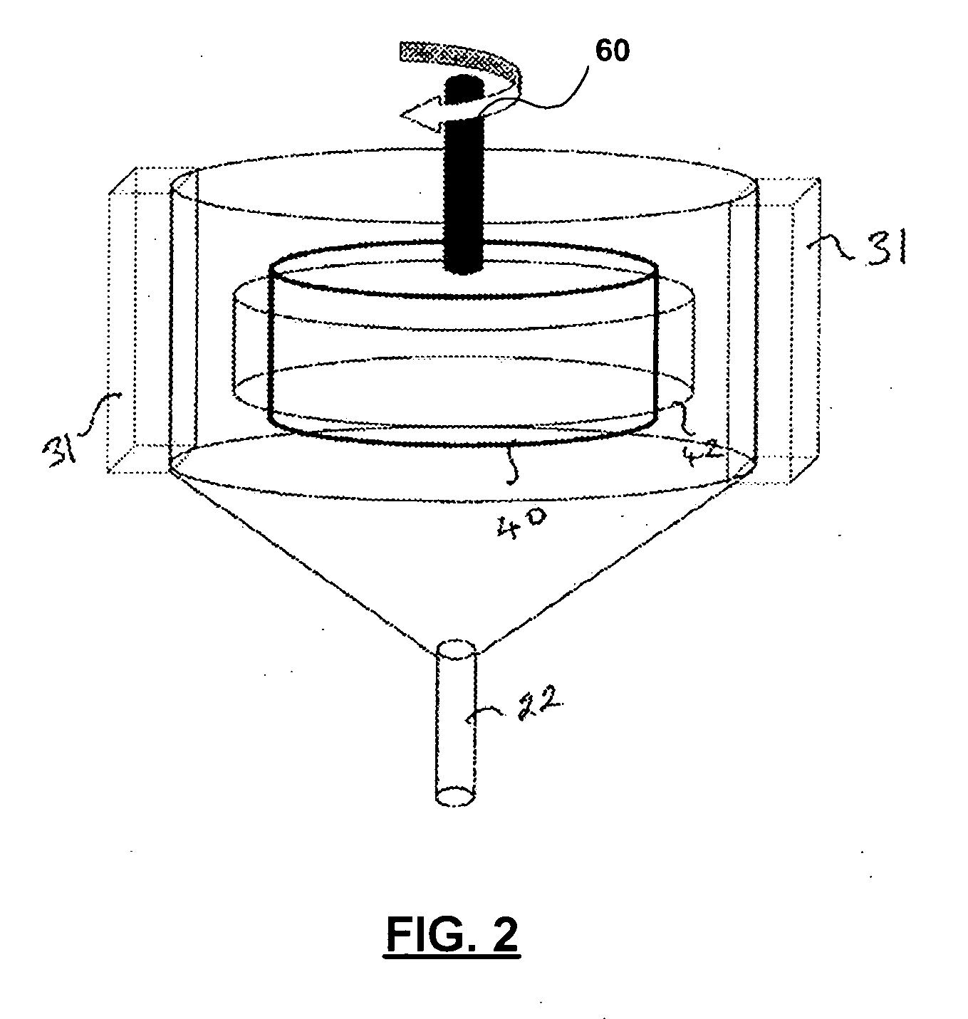
Electrolytic cell for removal of material from a solution

a technology of electrolysis cell and solution, which is applied in the direction of electrolysis organic production, electric furnace, furnace, etc., can solve the problem of inability to dislodge the material, achieve the effect of economic recovery of metals, avoid complex cleaning methods of conductive surfaces, and simplify separation

Inactive Publication Date: 2005-08-25
GLOBAL IONIX INC
View PDF44 Cites 20 Cited by
  • Summary
  • Abstract
  • Description
  • Claims
  • Application Information

AI Technical Summary

Benefits of technology

[0018] There are many advantages in using this invention. First, the invention allows the recovery of metals from diluted electrolytes, more specifically from solutions where the total metal concentration ranges from 0 to 3000 ppm, preferably between 20 to 500 ppm. The invention also provides economical recovery of metals from such solutions because metals are obtained in a form of a powder which can be removed from a rotatable electrode without using a mechanical device, such as a blade, to remove it. The powdery metal deposit is easily removed from the rotatable electrode with the use of ultrasonic energy. Then the removed powder metal can be recovered using an appropriate filtration system. This separation is further simplified when the rotatable electrode is cathodic.
[0019] Third, the use of ultrasonic energy to remove deposit from the rotatable electrode cleans this latter at the same time, hence, almost eliminating the use of mineral acids or other toxic chemicals to condition its surface for further use. Fourth, the ultrasonic device of the invention can also be used to clean the surface of the rotatable electrode from organic fouling when the rotatable electrode is polarized as an anode for electrooxidation, thus avoiding complex methods for cleaning its conductive surface. However, the equipment is designed such that the rotatable electrode can be raised. Thus can be inspected, cleaned or repaired at will.

Problems solved by technology

The applicants have found that it is not feasible to dislodge the material if it becomes deposited as a solid film.

Method used


Image

  • Electrolytic cell for removal of material from a solution
  • Electrolytic cell for removal of material from a solution
  • Electrolytic cell for removal of material from a solution

Examples


example 1

[0060] A solution containing 100 ppm of zinc from a zinc chloride plating solution is reduced to 15 ppm in two steps: the first step uses a current density of 80 mA / cm2 at a rotatable electrode whose tangential speed is 3.5-4.5 m / sec with a treatment time 1.33 times the flow rate; and the second uses half the current density of the first step but twice the time of treatment.

example 2

[0061] A solution containing 200 ppm of copper from an acid copper plating solution is reduced to 20 ppm with a current density of 60 mA / cm2 at a rotatable electrode with a tangential speed of 3.0-4.0 m / sec with a treatment time equal to 1.25 times the flow rate.

example 3

[0062] A solution containing 200 ppm of nickel from an acid nickel sulfamate plating solution is reduced to 30 ppm with a current density of 27 mA / cm2 at a rotatable electrode with a tangential speed of 2.5-3.5 m / sec with a treatment time equal to 1.50 times the flow rate.


PUM

PropertyMeasurementUnit
tangential speedaaaaaaaaaa
current densityaaaaaaaaaa
thickaaaaaaaaaa

Abstract

Disclosed is an electrolytic cell for removal of material from a solution. The cell comprises a cavity for receiving the solution, a rotatable electrode located within the cavity, a counter-electrode in spaced relation to the rotatable electrode, and an ultrasonic generator coupled to said cavity for directing ultrasonic energy toward the rotatable electrode to displace solid material extracted from the solution by an electrochemical reaction. The rotatable electrode may form a cathode, and the counter-electrode may form an anode, wherein metal in the solution is deposited on the cathode as a metal powder, such that the ultrasonic energy displaces the metal powder from the cathode. Alternatively, the rotatable electrode may form an anode, and the counter-electrode may form a cathode, wherein organic waste in the solution is deposited on the anode, such that the ultrasonic energy removes the deposited organic waste from the anode.

Description

CROSS REFERENCE TO RELATED APPLICATION [0001] This application claims the benefit under 35 USC 119(e) of U.S. provisional application No. 60 / 502,950, filed Sep. 16, 2003, the contents of which are herein incorporated by reference.FIELD OF THE INVENTION [0002] The present invention relates to an electrochemical method and apparatus for treating solutions either by electrowinning or electrooxidization. BACKGROUND OF THE INVENTION [0003] The concept of recovering materials from solutions by electrolysis is not new. Many industries, such as plating processes, mining processes and metal finishing, produce waste product of solutions containing ions of metals, and recovery of this metal is both environmentally and economically beneficial. Waste from solutions with unrecovered metal increases the amount of sludge disposed on land-fields. Many systems of metal recovery currently use a mechanical device, such as a blade, to remove deposited material from an electrode. The use of a mechanical ...

Claims


Application Information

Patent Timeline
Patent Type & Authority Applications(United States)
IPC IPC(8): C02F1/36C25B3/13C02F1/461C02F1/467C25B3/23C25C5/02C25C7/00C25C7/08
CPCC02F1/36C25C7/08C02F1/46109C02F1/467C02F1/4672C02F1/4678C02F2001/46119C02F2001/46123C02F2101/20C02F2101/30C02F2103/16C02F2201/46125C02F2201/4617C25C5/02C25C7/00C25C7/007C02F1/46104C25C5/00C02F1/461
Inventor HENUSET, YVES MICHEL
Owner GLOBAL IONIX INC
Why Eureka
Try Eureka