
Methods for treating membranes and separation facilities and membrane treatment composition

a technology of membrane treatment and separation facilities, applied in the direction of cleaning hollow articles, separation processes, liquid cleaning, etc., can solve the problems of filtration membranes that have a tendency to foul during processing, complex membrane fouling process, and almost all feed components to a certain exten

Active Publication Date: 2005-08-25
ECOLAB USA INC
View PDF61 Cites 120 Cited by
  • Summary
  • Abstract
  • Description
  • Claims
  • Application Information

AI Technical Summary

Benefits of technology

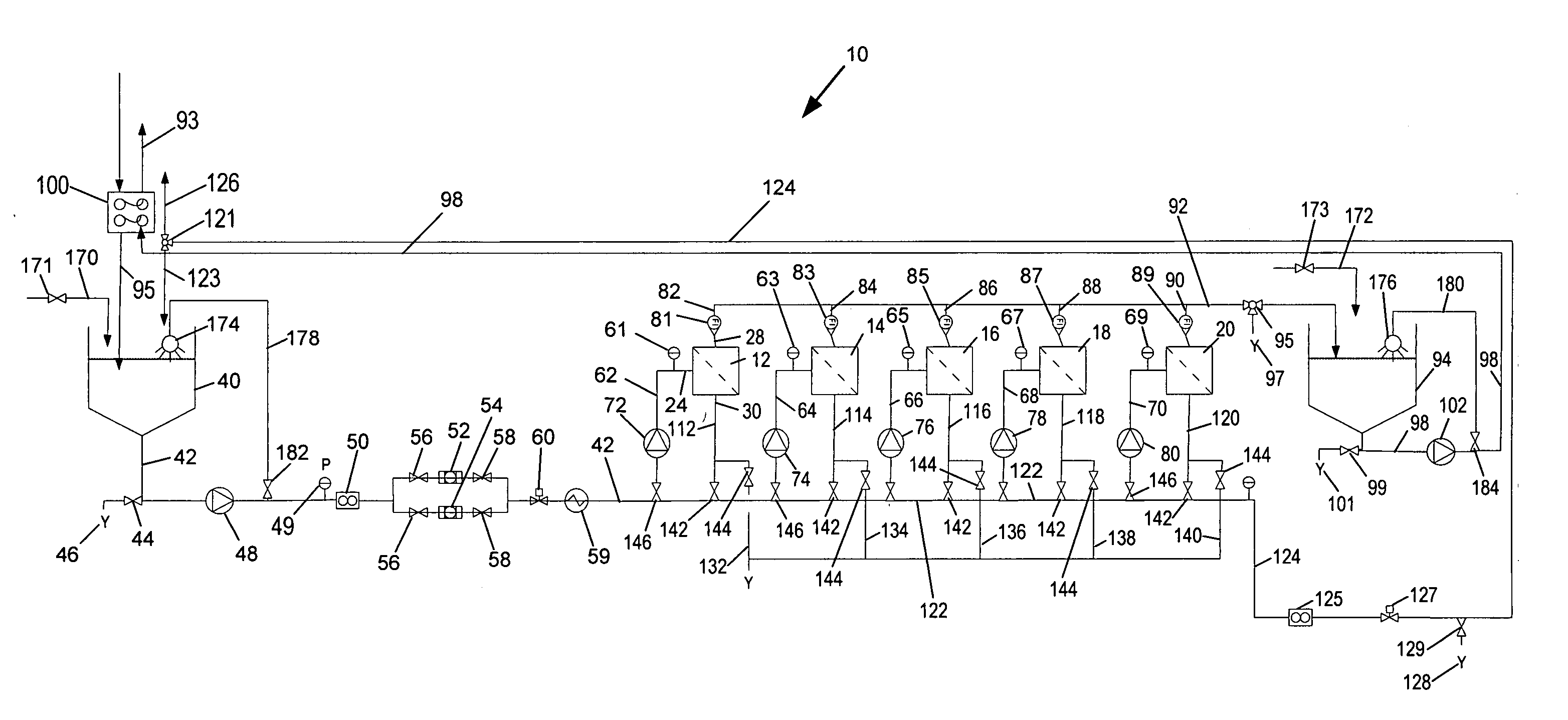
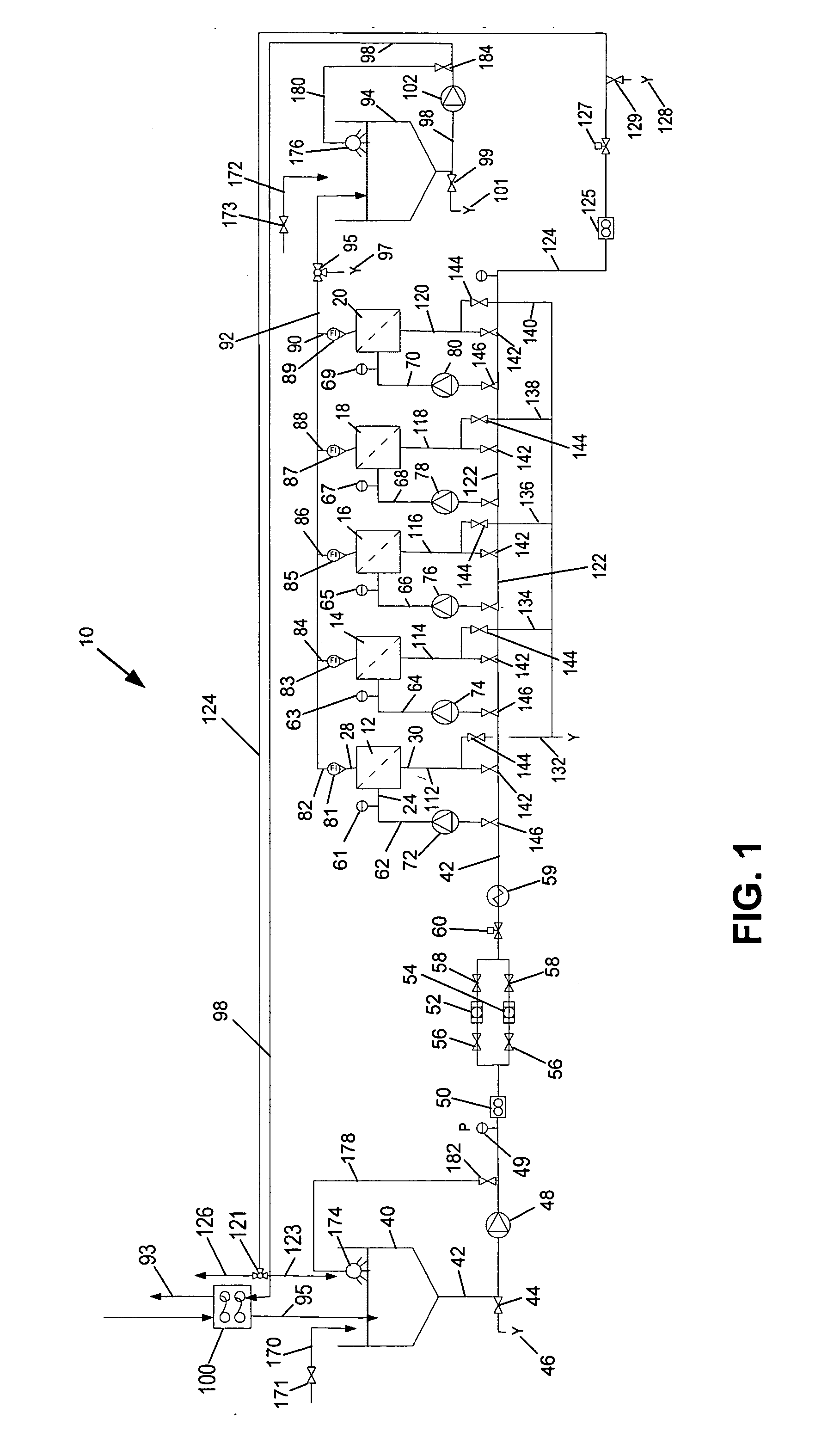
[0070] One advantage of the present invention is the ability to deliver a high concentration of a particular chemistry to a membrane to provide a desired effect. It is expected that using liquid flow to achieve the concentrations that can be provided by multiple phase flow may be too cost prohibitive. Accordingly, it is expected that there is very little literature describing the effect of highly concentrated compositions, such as those concentrations that can be relatively easily obtained as a result of multiple phase flow, on various filtration membranes. Accordingly, one would likely want to test compatibility at the intended use concentration level while also considering the pH, temperature, and length of contact. As an example, an ultrafiltration polysulfone membrane may have typical restrictions including a pH range of 2-11 and a temperature of less than about 130° F. Accordingly, one may wish to maintain the concentrated chemistry for concentrated application to the membrane within these restrictions. For example, a concentrated buffered enzyme composition having a pH of about 9.5 has been found to work well with this type of ultrafiltration polysulfone membrane.

Problems solved by technology

Filtration membranes have a tendency to foul during processing.
In general, membrane fouling is a complicated process and is believed due to a number of factors including electrostatic attraction, hydrophobic and hydrophilic interactions, the deposition and accumulation of feed components, e.g., suspended particulates, impermeable dissolved solutes, and even normally permeable solutes, on the membrane surface and / or within the pores of the membrane.
It is expected that almost all feed components will foul membranes to a certain extent.
In general, the greater the temperature of the cleaning the solution, the more effective it is as a cleaning treatment, although most membrane materials have temperature limitations due to the material of construction.
Many membranes additionally have chemical limitations.
For example, many polyamide reverse osmosis membranes have chlorine restrictions because chlorine can have a tendency to damage the membrane.

Method used


Image

  • Methods for treating membranes and separation facilities and membrane treatment composition
  • Methods for treating membranes and separation facilities and membrane treatment composition
  • Methods for treating membranes and separation facilities and membrane treatment composition

Examples


example 1

Exemplary Conventional Membrane Treatment

[0156] The following procedure was performed on an ultrafiltration membrane to document a conventional treatment. The membrane was analyzed and soiled as the above procedures describe. After soiling, the flux decrease to 7% of the original value indicating a severely soiled membrane. Table 4 describes the treatment parameters. During this treatment process the inlet pressure was 30 psig and the outlet pressure was 15 psig creating a cross-flow process. These parameters resulted in a total flow rate of about 30 gallons per minute. Table 5 describes the treatment results where “% Flux Recovery” is a direct measurement of the efficacy of the treatment. Using conventional procedures and Ultrasil chemistry from Ecolab, Inc., the % Flux Recovery was 82% which for a new membrane is quite typical. [0157] Membrane type=Ultrafiltration, polyethersulfone [0158] Manufacturer / Model=GE Osmonics, PW3838C Durasan [0159] Pressure (in)=30 psig [0160] Pressure...

example 2

[0164] A hybrid membrane treatment utilizing both conventional cross-flow treatment and multiple phase air / liquid treatment was evaluated. The ability to use a higher concentration of buffered enzyme product was also evaluated. This highly concentrated chemistry was approximately ten times the typical use concentration and had a pH of 9.62 which is within the pH limitations of these particular UF membranes. After soiling, the membrane had a flux of 6% of the clean water flux indicating a severely soiled membrane. In this example a single-pass multiple phase treatment was performed during the alkaline / enzyme step meaning the solution was not re-circulated, but rather passed over the membrane and then to drain. Table 6 describes the treatment parameters and Table 7 provides the results of the treatment as measured by permeate flux. Using the conventional and multiple phase flow hybrid approach with the higher concentration of chemistry resulted in a 90% flux recovery using 16 minutes ...

example 3

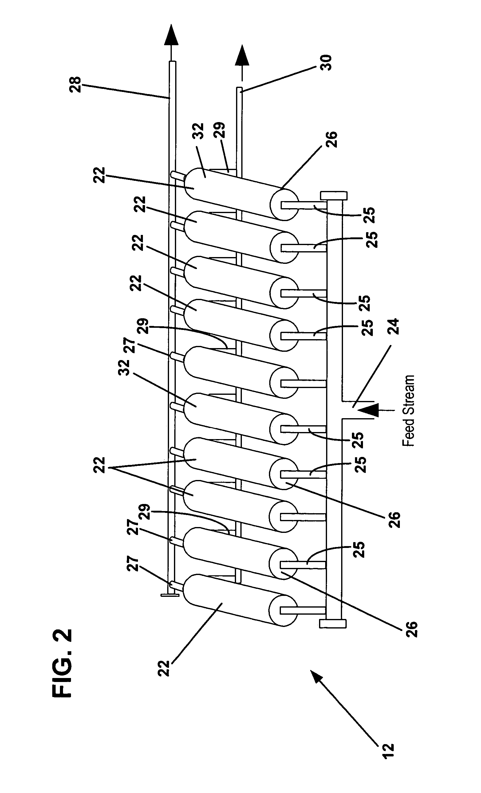
[0166] Various liquid injection rates and air flow rates were tested to determine a reasonably low air and liquid combination while still obtaining adequate coverage of the ultrafiltration membrane. This was a visual observation based upon the flow and converage of the liquid out of the downstream end of the membrane. It was also intended to ensure that the majority of air and liquid does not permeate. After observing various test parameters, it was determined that the conditions of air delivery at 10 psig and liquid flow of 0.38 gpm resulted in a good atomized flow from the downstream end of a single 4 inch diameter by 38 inch long polysulfone membrane. This results in an air volume of about 20 scfm, a velocity of about 2-4 fps and an air to liquid ratio of about 183:1 to 307:1.


PUM


Abstract

A method for treating a separation facility is provided according to the invention. The separation facility includes a plurality of membranes for providing separation of a feed product. The method includes steps of providing liquid flow through a plurality of membranes; treating the plurality of membranes with a multiple phase treatment composition comprising a gaseous phase and a liquid phase at a volumetric ratio of the gaseous phase to the liquid phase of at least about 5:1; and providing a liquid flow through the plurality of membranes.

Description

FIELD OF THE INVENTION [0001] The invention relates to methods for treating membranes using multiple phase flow, methods for treating separation facilities using multiple phase flows, and treatment compositions. Membranes provided within a separation facility can be treated using multiple phase flow to provide flushing, rinsing, pretreatment, cleaning, sanitizing and preserving. BACKGROUND OF THE INVENTION [0002] The use of a two-phase liquid / gas stream to clean pipelines is disclosed in European Patent Application 0 490 117 A1 to Kuebler that was published on Jun. 17, 1992 as an alternative to conventional clean-in-place techniques in order to reduce the amount of chemicals used. Kuebler describes cleaning pipelines using a two-phase liquid / gas stream and a reduction in throughput of the cleaning liquid by several orders of magnitude relative to conventional clean-in-place techniques. According to Kuebler: [0003] If two phases, namely liquid and gas, flow through a pipeline, then e...

Claims


Application Information

Patent Timeline
Patent Type & Authority Applications(United States)
IPC IPC(8): B01D65/00B01D65/02B01D65/06B01D67/00B08B9/02
CPCB01D65/00B01D65/02B08B9/0321B01D67/0097B01D2321/164B01D65/025
Inventor SCHACHT, PAUL F.MCBROOM, AMY B.HEI, ROBERT D.P.STAUB, RICHARD K.KRACK, RALFFERNHOLZ, PETER J.SOMAYAJULA, SRINIVAS
Owner ECOLAB USA INC
Learn More