Random number generator and probability generator

a probability generator and random number technology, applied in the field of random number generators, can solve the problems of large circuit scale, complex circuit structure, increased expected cost, etc., and achieve the effect of high stability and high performan

Active Publication Date: 2005-09-01
FDK CORP
View PDF6 Cites 36 Cited by
  • Summary
  • Abstract
  • Description
  • Claims
  • Application Information

AI Technical Summary

Benefits of technology

[0006] An object of the invention is to provide a random number generator and a probability generator having high performance and high stability, which realizes generation of a natural random number by a structure of a digital circuit, so that the problem of the prior art, that is, the problem of uniformity, regularity, correlativity, periodicity and the like is resolved.

Problems solved by technology

However, in the random number / probability generating circuit using the random pulse by the above natural phenomenon, since analog components, such as a generating source of the random pulse, an amplifier of a signal, waveform shaping, and an optimizing circuit of uniformity, are much included, the circuit scale becomes large and complicated, and accordingly, it is difficult to mount these as an integrated logic LSI, and it also becomes disadvantageous for application to a microminiature and thin high-tech equipment, such as an IC card, the demand of which is expected to be increased in future.
Besides, since the formation as an LSI is difficult, the productivity is poor and the cost becomes high.
Especially, since one using the thermal noise is apt to be influenced by an external noise, power supply fluctuation, temperature or the like, there is a defect that it is lacking in operation stability.
Besides, with respect to one using radiation, since there is a fear that the radiation influences the environment or the like even though it is extremely weak, the amount of usable radiation has a limit, and it has been difficult to cope with such a use that a lot of random numbers are generated in a short time.

Method used


Image

  • Random number generator and probability generator
  • Random number generator and probability generator
  • Random number generator and probability generator

Examples


first embodiment

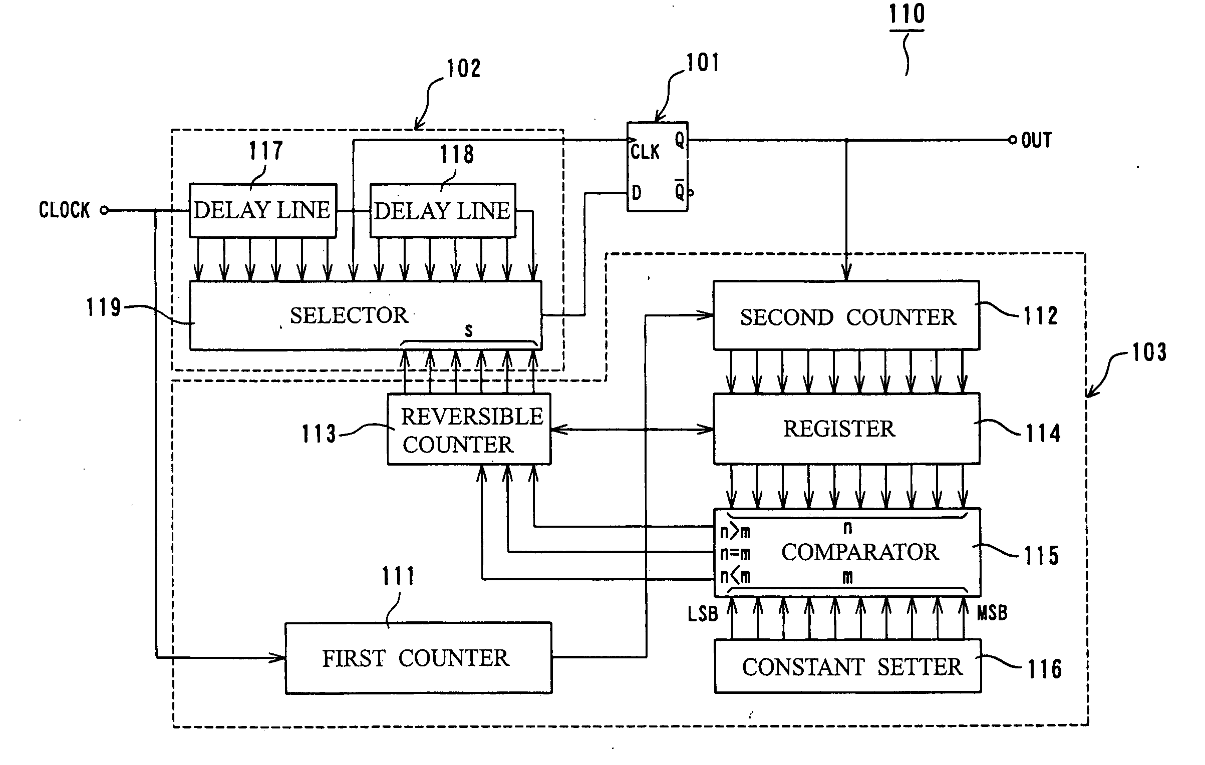
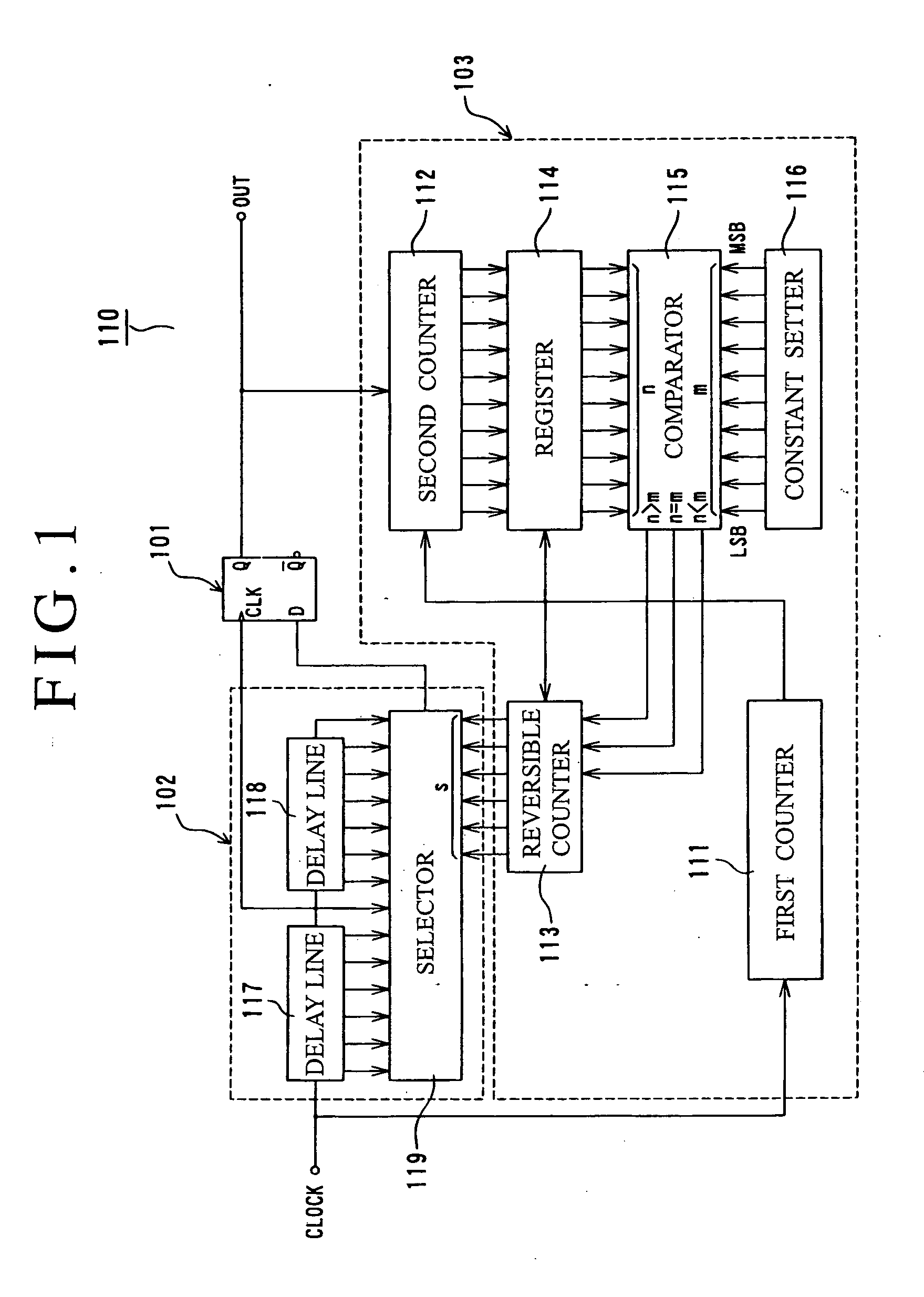
[0168]FIG. 1 is a circuit diagram showing a random number generator.

[0169] As shown in FIG. 1, a random number generator 110 of the first embodiment is constituted by a flip-flop 101, a delay unit 102, and a feedback circuit 103.

[0170] Here, a flip-flop having such a function that an output state (0 or 1) becomes definite according to a phase difference between input signals (CLOCK) inputted to two input units can be used as the flip-flop 101, and this embodiment uses a D-type flip-flop provided with a clock terminal CLK and a data terminal D for signal input and shown in FIG. 13.

[0171] Besides, the delay unit 102 includes plural delay output terminals, and is constituted by two delay circuits 117 and 118 (delay line) connected in series to each other, and a selection circuit 119 (selector) for selecting any one of the delay outputs according to a select input. A connection point (which becomes a delay intermediate point) of the two delay circuits 117 and 118 is connected to the c...

second embodiment

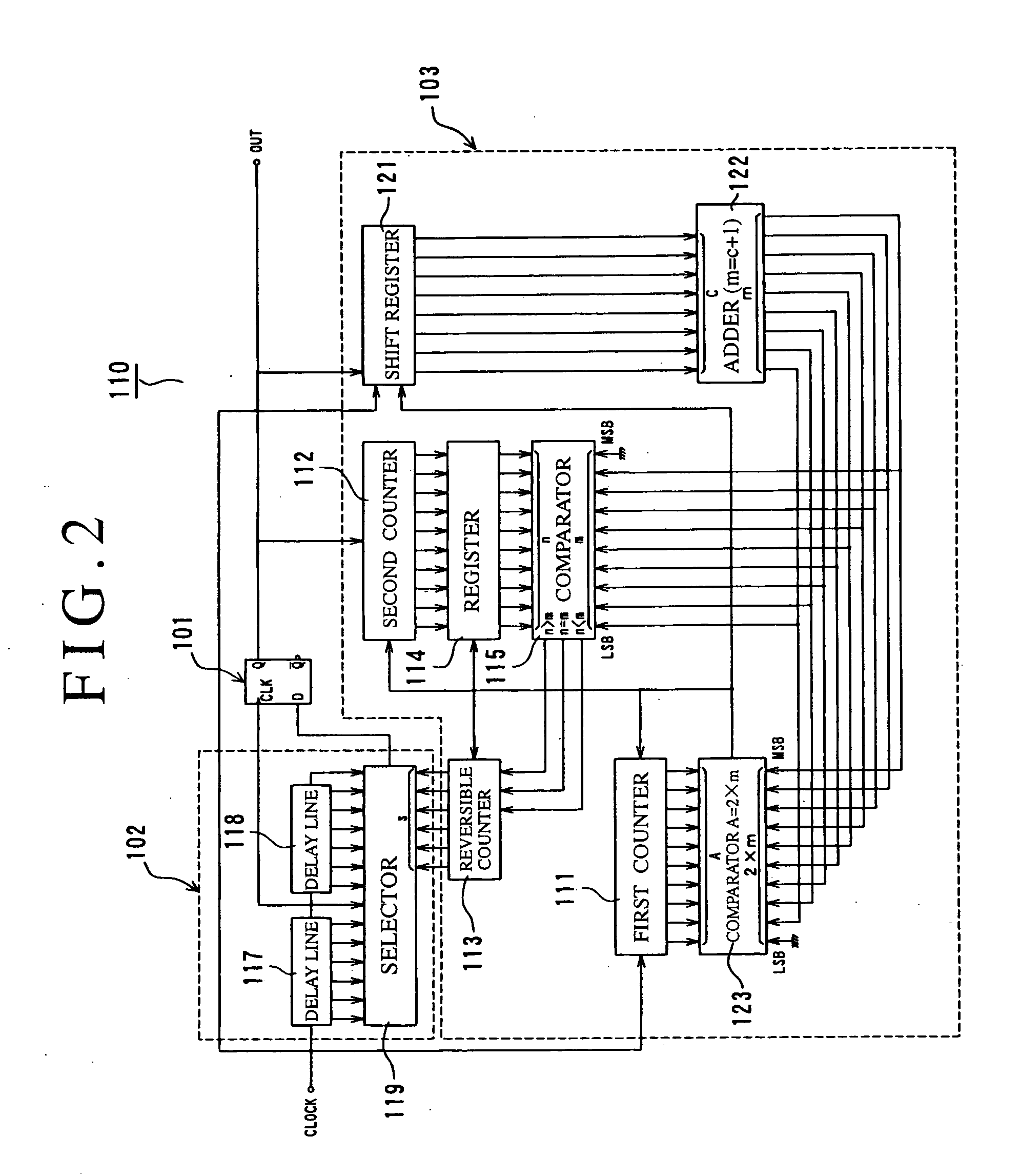
[0177] First, the second embodiment shown in FIG. 2 is an example in which instead of the foregoing constant setter 116, a shift register 121, an adder 122, a comparator 123, and the like are newly provided, and a random number sequence outputted every repetition cycle is made setting data (2×m) of a next repetition cycle and comparison data (m) of a comparator 115. Incidentally, the adder 122 adds 1 to a range of output random numbers (0 to m−1) to change it to a range of (1 to m) in order to use the random number sequence as the setting data and the comparison data. Besides, the new comparator 123 generates a repetition cycle (2×m) from count data (A) of the first counter 111 and output data (m) of the adder 122.

[0178] Next, a third embodiment shown in FIG. 3 is an example in which a scramble circuit 124 is added to the second embodiment, and an outputted random number is further scrambled and is used as the setting data and the comparison data. Incidentally, the term “scramble” m...

third embodiment

[0231] Next, a third embodiment in the second mode of the invention will be described.

[0232] As shown in FIG. 44, a random number generator of the third embodiment is constituted by an R-S flip-flop 216 for outputting a one-bit serial random number RND, delay circuits 202 and 203 connected to an S terminal and an R terminal of the R-S flip-flop 216, and a not-shown phase control circuit 205 (see FIGS. 15 and 16).

[0233] Here, FIG. 45 shows an internal circuit of the R-S flip-flop constituted by N-channel MOS transistors and P-channel MOS transistors. An S side NAND gate circuit is constituted by transistors Q1 to Q4, and an R side NAND gate circuit is constituted by transistors Q5 to Q8.

[0234] In an edge trigger type flip-flop such as, for example, an R-S flip-flop, it is known that when a rising phase difference between an S side input signal and an R side input signal is made to approach 0, a metastable phenomenon occurs, and when this phenomenon occurs, it takes a time for a fli...


PUM


Abstract

A random number generator includes a flip-flop in which an output state (0 or 1) becomes definite according to a phase difference between signals inputted to two input units, a delay unit for producing the phase difference in these two input signals, and a feedback circuit for controlling the phase difference so that an occurrence ratio of 0 or 1 of an output from the flip-flop by the input signals is constant within a specified repetition cycle.

Description

TECHNICAL FIELD [0001] The present invention relates to a random number generator suitable for use in scientific calculation, a game machine, encryption processing or the like, and a probability generator constructed by using this random number generator. Further, the invention relates to a random number generator in which a phase difference between two input signals inputted to a flip-flop is automatically adjusted so that an occurrence ratio of 0 or 1 of an output from the flip-flop becomes constant, and particularly to efficient phase adjustment means. BACKGROUND OF THE INVENTION [0002] It is indispensable to use a random number for high level scientific calculation, a game machine, encryption processing or the like, and in recent years, the demand for a high performance generator of a natural random number (true random number) with uniformity (a difference in occurrence ratio is not produced according to a random number) and without regularity of random number occurrence, before...

Claims


Application Information

Patent Timeline
Patent Type & Authority Applications(United States)
IPC IPC(8): G06F1/02
CPCG06F7/588
Inventor YAMAMOTO, HIROYASUSHIMIZU, TAKAKUNIVITHANAGE, ANANDAKOIBUCHI, MISAKOSOGA, RYUJISHIGA, TAKAAKI
Owner FDK CORP
Why Eureka
Try Eureka