Slab type solid-state laser medium and slab type nonlinear optical medium each using light path formed by multiple reflection caused by three reflecting surfaces

a laser medium and slab type technology, applied in the direction of optical resonator shape and construction, active medium materials, instruments, etc., can solve the problems of low energy conversion efficiency of the lamp itself from electricity to light, deficiency of the device excitation type in utilization efficiency of excitation light, emission spectrum, etc., to eliminate the burning of spatial holes, high output, and high dimensional accuracy

Inactive Publication Date: 2005-09-08
NAT INST OF INFORMATION & COMM TECH
View PDF5 Cites 15 Cited by
  • Summary
  • Abstract
  • Description
  • Claims
  • Application Information

AI Technical Summary

Benefits of technology

[0040] Further, the fact that a multiple light path is formed in the laser medium and disposed accurately brings, in the conventional laser device, the effect of eliminating the spatial hole burning which occurs, for example, in the laser device configured by combining a laser medium with a Fabry-Perot (FP) resonator. It is known that the spatial hole burning renders the simple vertical mode oscillation difficult to occur. In the laser medium according to this invention, the spatial hole burnings generated by the standing wave of the laser beam are enfeebled by overlapping in numerous directions. Heretofore, the manufacture of a single-frequency solid-state laser width high output has never been successful unless the contrivance, such as a one-way ring resonator incapable of generating a spatial hole burning is used. By using the laser medium which has light paths disposed as contemplated by this invention, however, it is made possible to obtain the laser oscillation of a single frequency with high output even by the use of a standing wave type laser resonator. That is, the individual sections of the light path forming the multiple light path are overlapped while the positions and the directions thereof are spatially changed little by little. This fact brings the effect of averaging or compensating the various forms of lack of uniformity of spatial hole burning and excitation distribution and refractive index profile in the laser medium.
[0041] Further, the laser medium of this invention has the form of a basically triangular prism and uses the three side faces of the prism as optical surfaces. The triangular prism is characterized by having the shape thereof decided exclusively by the angles between these optical surfaces. The manufacture of the conventional zigzag slab laser medium necessitates high dimensional accuracy and high angular accuracy. The manufacture of the laser medium in this invention has no need for high dimensional accuracy as described above. The angular accuracy which is required may be such as is necessary for the production of an inexpensive triangular prism. The device of this invention, for the sake of simple production, is completed by the treatment of optical polishing given to the three surfaces and the formation of an optical film on the two surfaces. Generally, the polishing step can easily reach the angular accuracy of surfaces but cannot easily reach the highly accurate spacing of planes. The laser medium or the nonlinear optical device contemplated by this invention chiefly necessitates the angular accuracy exclusively. It does not necessitate high manufacturing accuracy because the error of the angles of surfaces can be corrected by the adjustment of the angle of incidence. Thus, it enjoys the advantage of easy manufacture.

Problems solved by technology

1) The devices of the lamp excitation type are deficient in utilization efficiency of excitation light because the energy conversion efficiency of the lamp itself from electricity to light is low, the emission spectrum of the excitation lamp is wide and the spectrum ineffective in the laser operation is copious.
These laser devices as a whole, therefore, are deficient in efficiency of energy utilization and necessitate a large electric power for obtaining a necessary amount of output as compared with the laser devices of the other excitation type.
These devices, however, possess a part which constitutes a bottleneck in the energy conversion from the excitation light to the laser beam as described herein below.
The formation of the part constituting the bottleneck as described above is ascribable to the fact that the laser medium cannot completely absorb the excitation light efficiently because the active ions of the solid-state laser have a small cross section for absorbing the excitation light and the fact that the energy stored in the laser rod cannot completely be converted efficiently into the laser beam because the cross section of induced emission is small and the laser gain is consequently small.
The increase of this doping level, however, tends to result in degrading the quality of the laser medium by disrupting the uniformity of the doping concentration and the refractive index distribution during the stage of manufacturing the laser medium and decreasing the life time of the ions at upper energy levels.
The doping level of the laser active ions is limited because the degradation results in deteriorating the transverse mode of the laser beam and lowers the performance of the laser medium.
The limit mentioned above arises because an effort to preclude the problem and obtain the fundamental transverse mode oscillation results in necessitating a decrease in the doping amount of the active ions in the laser medium with the object of lowering the density of heat generation, for example.
Since the exaltation of the excitation volume and the contraction of the mode volume are mutually contradicting conditions, however, the conformity of these conditions is difficult to achieve in the conventional laser medium through which the laser beam advances straight and passes singly.
These configurations, however, have been at a disadvantage in complicating the structure of a laser device and suffering the laser device to occupy a large size because they add to the number of optical components forming a multiple light pass and necessitate precise adjustment for the sake of necessary operation.
This loss is accumulated when the laser beam reciprocates through the light path and the accumulated loss results in diminishing the effect of exalting the laser gain brought by means of the multiple light path.
Such light paths, however, are at a disadvantage in rendering their configuration difficult to achieve.
Thus, they either fail to acquire satisfactory wavelength conversion efficiency or necessitate a powerful laser beam for the sake of obtaining a necessary output.
It is not easy to produce a large uniform crystal.
Conventional configuration has been at a disadvantage in complicating the structure of the laser device and suffering the device to occupy large dimensions because the number of optical components for forming the multiple light path increases and the device needs precise adjustment for the operation as expected.
This optical loss has diminished the effect of augmenting the laser gain each time the laser beam reciprocates through the light path.
The conventional configuration has been further at a disadvantage in failing to form a multiple light path having light paths so extensively disposed as to fill up the interior of the laser rod because the multiplicity of light paths have their individual directions change only slightly.
Thus, the wavelength conversion devices have been unable to acquire sufficient wavelength conversion efficiency.

Method used


Image

  • Slab type solid-state laser medium and slab type nonlinear optical medium each using light path formed by multiple reflection caused by three reflecting surfaces
  • Slab type solid-state laser medium and slab type nonlinear optical medium each using light path formed by multiple reflection caused by three reflecting surfaces
  • Slab type solid-state laser medium and slab type nonlinear optical medium each using light path formed by multiple reflection caused by three reflecting surfaces

Examples


embodiment 1

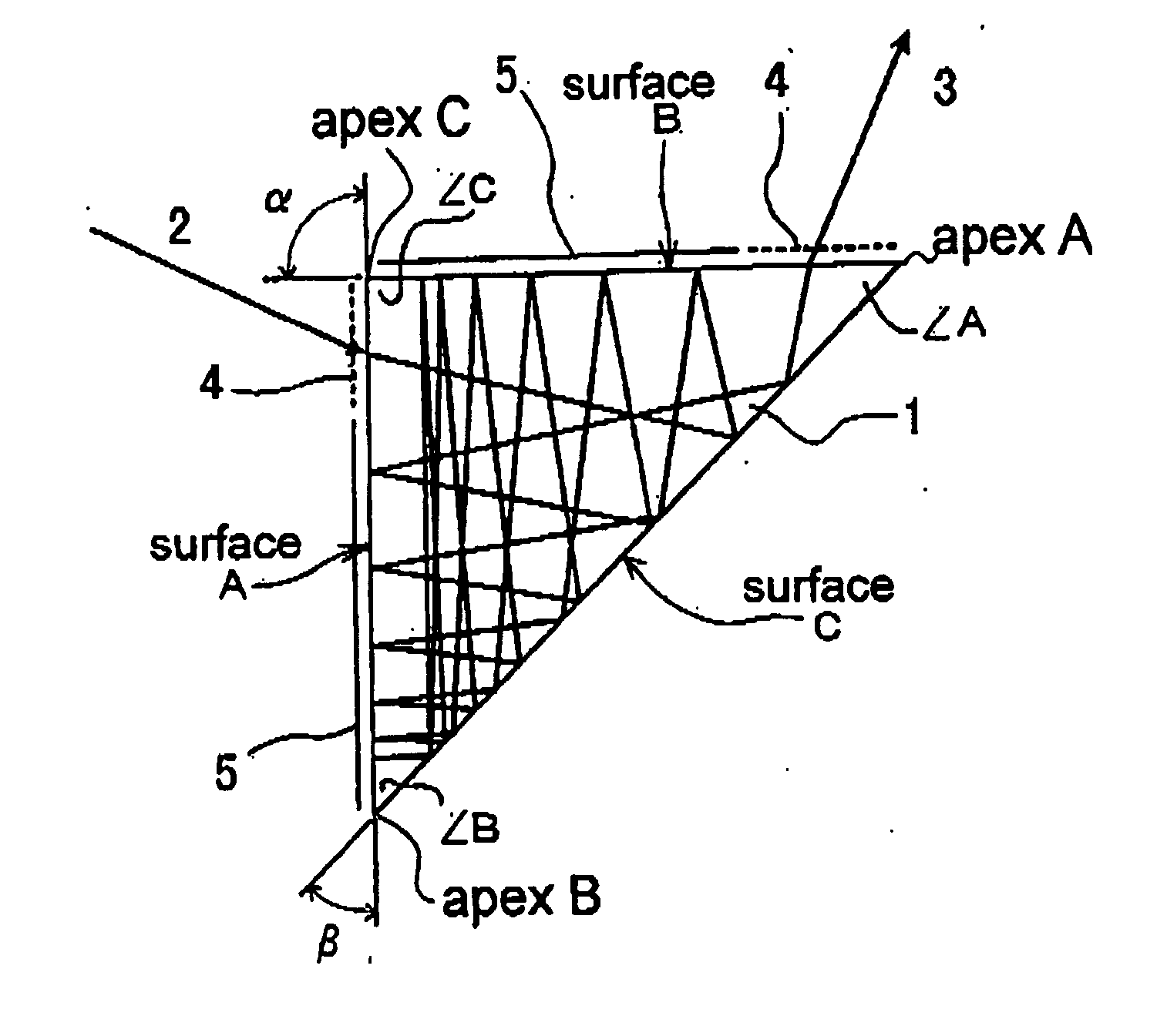
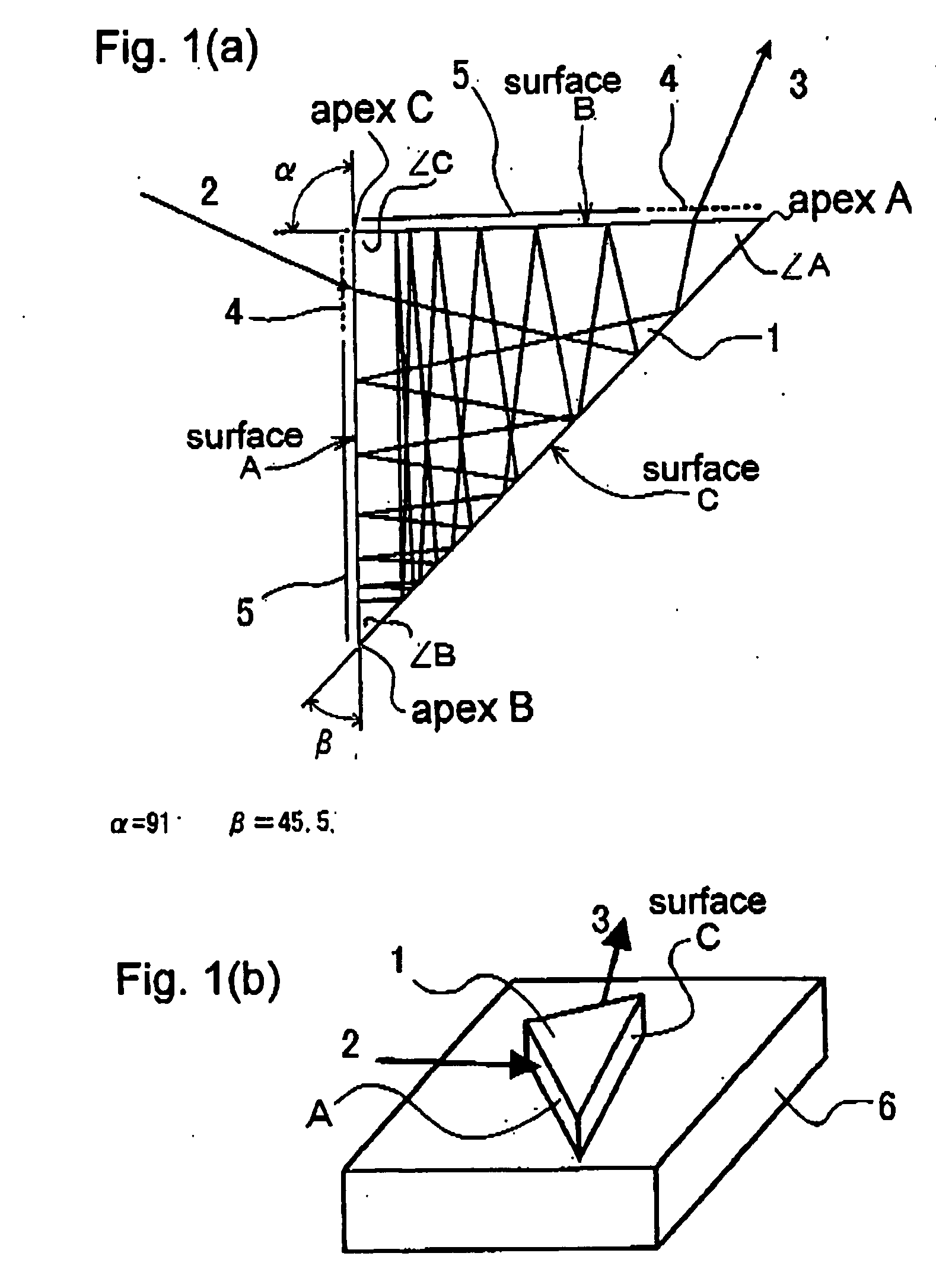
[0071] First, an embodiment of this invention will be described with reference to FIG. 1. The solid-state laser medium (laser rod) of this invention, as illustrated by a plan view in FIG. 1(a) and by a perspective view in FIG. 1(b), is a slab 1 of the form of a triangular prism using a Nd:YAG crystal. The slab has an upper and a lower triangular surface and quadrangular side face A (hereinafter described as “Surface A”), side face B (hereinafter described as “Surface B”) and side face C (hereinafter described as “Surface C”) lying orthogonal thereto. Surfaces A, B and C are optically polished surfaces which are furnished thereon an antireflection coating and a reflecting film depending on the purposes of use of the relevant positions. The bottom face of the slab is bonded tightly to a heat sink 6 for cooling. On at least either of Surface A and Surface B which include a vertex A of an angle a approximating the right angle, a part for injecting the laser beam as an incident light 2 o...

embodiment 2

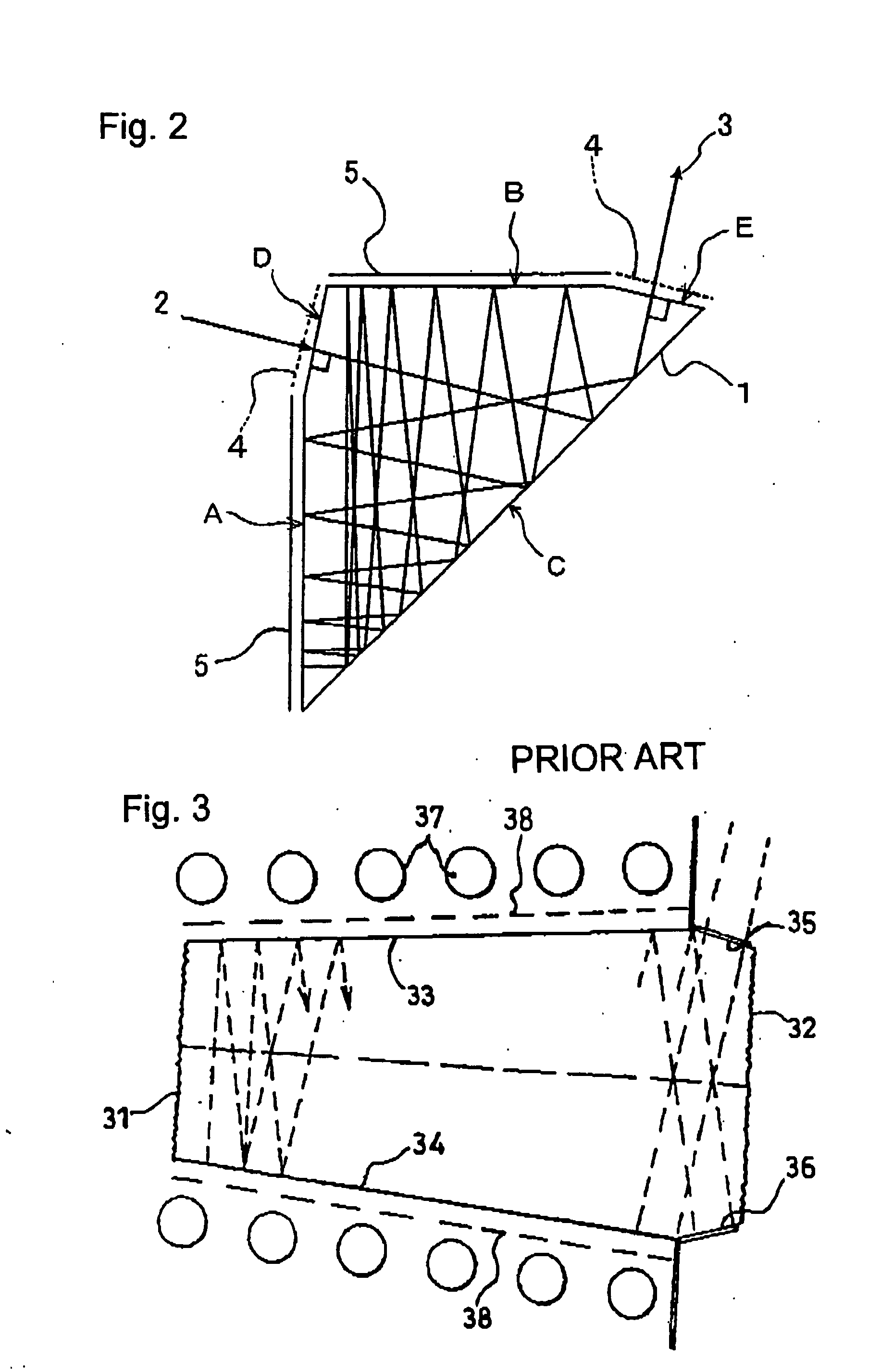
[0114] In the disposition of a light path in which the incident light and the emitted light of the solid-state laser medium coincide, a monolithic solid-state laser is formed by altering the injection and emission parts of Surface A to a spherical surface 12 having attached thereto a diffusion shell 13 as illustrated in FIG. 21. The monolithic solid-state laser can be similarly formed by furnishing Surface B (not Surface A) with a spherical output part. It is evident that the monolithic solid-state laser is similarly formed by imparting a flat surface or a spherical surface to the surfaces corresponding to Surface D or Surface E added anew to the side face of the slab as the incident part and the emission part of Surface A and Surface B of FIG. 2 and altering them to the surfaces having a diffusion shell and a highly reflecting film attached thereto, respectively.

embodiment 3

[0115] By connecting the solid-state laser media in series as illustrated in FIG. 22 or FIG. 23, it is made possible to obtain a still higher laser gain and a laser beam of high output. It is evident that a ring laser can be easily configured by so adding reflectors to the configuration of FIG. 22 or FIG. 23 as to circulate the light path therethrough.


PUM

PropertyMeasurementUnit
anglesaaaaaaaaaa
Brewster angleaaaaaaaaaa

Abstract

A slab type solid-state laser medium furnished on side faces thereof with three reflecting surfaces, provided therein with a light path for optical amplification attained by multiple reflection on the reflecting surfaces, wherein the three reflecting surfaces comprises Surface C serving as a surface on which an incident laser beam reflects first in the solid-state laser medium, Surface B serving as a surface on which the beam reflected on Surface C is subsequently reflected and Surface A serving as a remaining surface, and wherein when Surface Ac and Surface Bc respectively denote imaginary surfaces forming reflected images of Surface A and Surface B relative to Surface C and when Angle C denotes an angle of intersection between Surface A and Surface B or extended surfaces thereof, Angle A denotes an angle of intersection between Surface B and Surface C or extended surfaces thereof and Angle B denotes an angle of intersection between Surface C and Surface A or extended surfaces thereof, Angle C is larger than each of Angle A and Angle B and the incident laser beam is injected into the solid-state laser medium so that the light path formed for the optical amplification in the solid-state laser medium is equivalent to a light path in which the injected beam repeating reflection between Surface A and Surface Bc has been folded back at Surface C, whereby the light path is capable of producing unit reflections on Surface C, Surface B, Surface C and Surface A sequentially in the order mentioned and inducing a multiplicity of the unit reflections. Otherwise, for the purpose of inducing a nonlinear optical effect, a slab type nonlinear optical device similar in shape to the solid-state laser medium is used in the place of the solid-state laser medium.

Description

BACKGROUND OF THE INVENTION [0001] 1. Field of the Invention [0002] This invention relates to a solid-state laser medium using a light path formed by multiple reflection caused by three reflecting surfaces which is usable in a compact high-power solid-state laser device and to a nonlinear optical medium using a light path formed by multiple reflection caused by three reflecting surfaces which is small and capable of high conversion efficiency due to a nonlinear optical effect. [0003] 2. Description of the Prior Art [0004] The conversion efficiency from the electric power input to the light output of a solid laser device constitutes one of the most important properties of the laser. The conventional solid-state laser devices of the lamp excitation type and the laser diode (LD) excitation type have incurred the following problems. [0005] 1) The devices of the lamp excitation type are deficient in utilization efficiency of excitation light because the energy conversion efficiency of th...

Claims


Application Information

Patent Timeline
Patent Type & Authority Applications(United States)
IPC IPC(8): G02F1/37H01S3/06G02F1/35H01S3/07H01S3/08H01S3/083H01S3/094H01S3/0941H01S3/109H01S3/113H01S3/16H01S3/23
CPCG02F1/3523H01S3/2325H01S3/0606H01S3/0615H01S3/0621H01S3/07H01S3/08095H01S3/083H01S3/094084H01S3/0941H01S3/109H01S3/113H01S3/1611H01S3/1643G02F2201/17
Inventor ISHIZU, MITSUO
Owner NAT INST OF INFORMATION & COMM TECH
Why Eureka
Try Eureka