
Polishing slurry, method of producing same, and method of polishing substrate

a technology of polishing slurry and substrate, which is applied in the field of polishing slurry, can solve the problems of uneven surface flattening, excessive volume removal of oxide layer, and discoloration phenomenon, and achieve the effect of stabilizing dispersion

Active Publication Date: 2005-09-15
IUCF HYU (IND UNIV COOP FOUNDATION HANYANG UNIV) +1
View PDF11 Cites 20 Cited by
  • Summary
  • Abstract
  • Description
  • Claims
  • Application Information

AI Technical Summary

Benefits of technology

[0015] Another object of the present invention is to provide a slurry having an optimum polishing particle size, in which the polishing particle size is controlled and which is useful to produce semiconductors having fine design rules, by changing the production conditions of the slurry. Furthermore, the present invention provides a polishing slurry and a method of producing the same, in which a desirable CMP removal rate is assured and scratches are suppressed, by controlling a polishing particle size distribution.
[0016] Still another object of the present invention is to provide a method of effectively polishing a semiconductor substrate having a fine design rule using the above slurry. In order to accomplish the above objects, the present invention provides a polishing slurry comprising polishing particles, which have a particle size distribution including separated fine and large polishing particle peaks. The polishing particles include secondary particles having a median size of 50-450 mm, the secondary particles include primary particles having a median size of 50-300 nm, and the primary particles include grains having a median size of 50-150 nm.
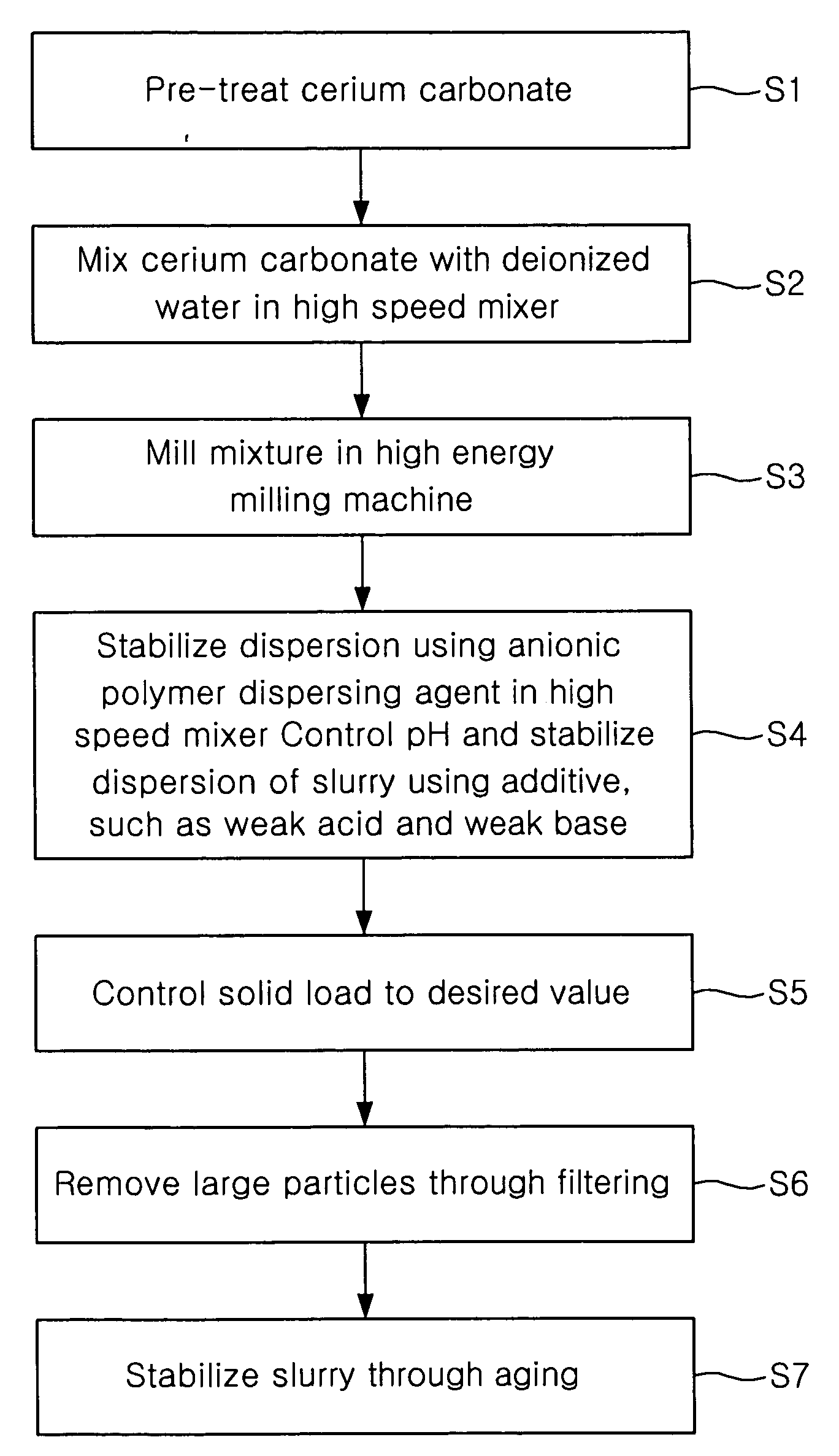
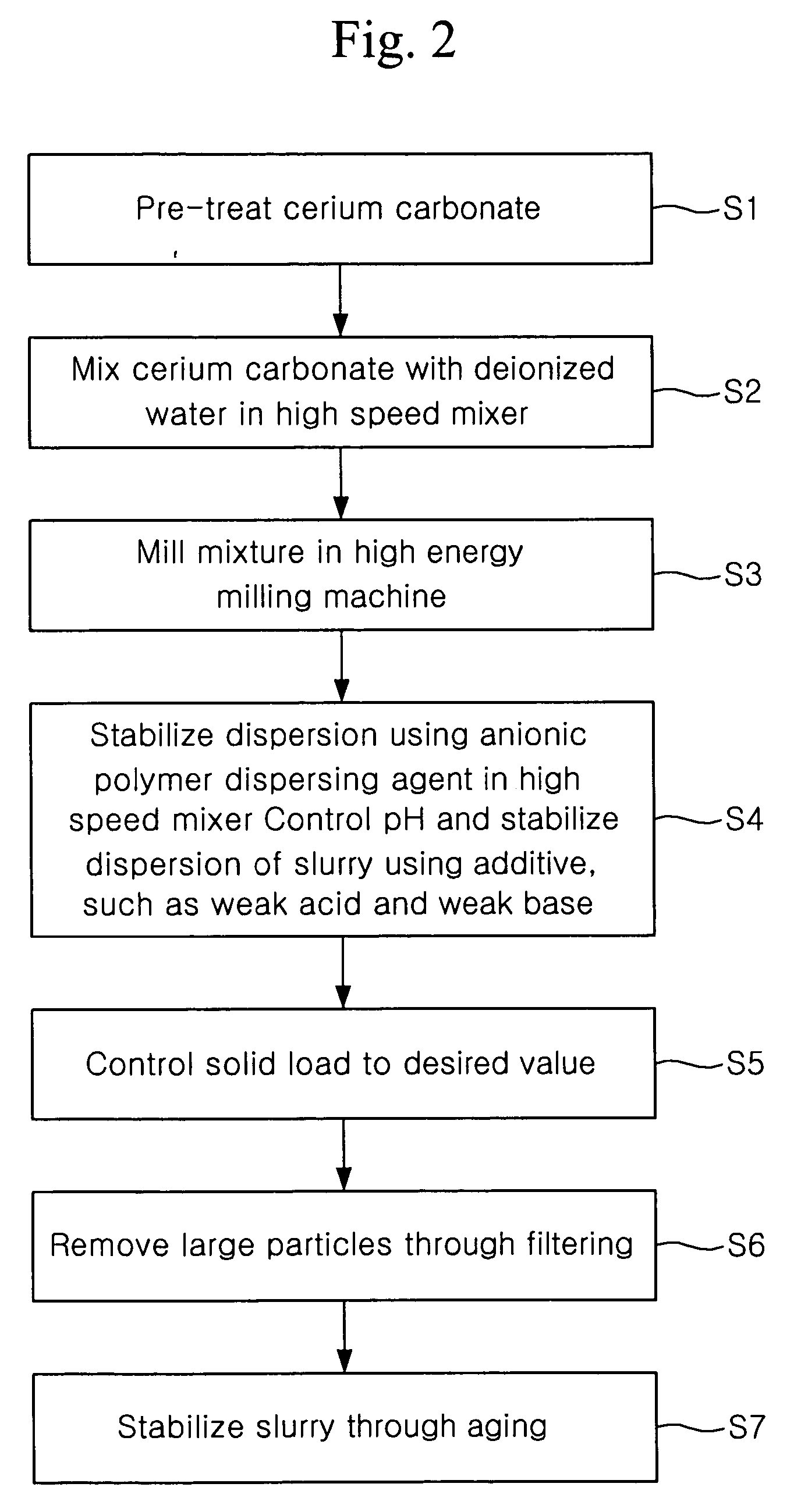
[0022] The method may further comprise steps of mixing the polishing particles with deionized water and milling them, stabilizing dispersion by adding a dispersing agent and an additive to the milled mixture slurry, and controlling a weight of the resulting mixture slurry and removing large particles by filtering.

Problems solved by technology

If polishing speed selectivity of the oxide layer to the nitride layer is low, generally, a dishing phenomenon, in which an excessive volume of the oxide layer is removed, occurs due to the loss of adjacent nitride layer patterns.
Thus, it is impossible to achieve uniform surface flattening.
However, the use of the additive is disadvantageous in that the removal speed of the oxide layer, as well as the removal speed of the nitride layer, is reduced.
Furthermore, the polishing particles of the ceria slurry are typically larger than those of the silica slurry, and therefore scratch the surface of the wafer.
However, the average particle size and the particle size distribution of the slurry particles suggested by conventional technologies are problematic in that, since the particles are large, if the slurry particles are used to produce semiconductors having fine design rules, many micro-scratches may be formed.
With respect to this, if the large particles are removed through simple filtering in order to form a slurry having no scratches, consumption of filters increases and reproducibility is poor.
Additionally, conventional technologies disclose only the average particle size of polishing particles constituting the slurry and the distribution of the polishing particles, but not the effects of the specific size distribution of the slurry particles within the given average particle size range on the removal rate of STI CMP or on the creation of scratches.
As well, they do not disclose other characteristics of the slurry produced under process conditions generating the given size distribution.
Further, they do not disclose the effects of processes of producing slurries having different properties or of conditions of slurries depending on the processes to CMP.

Method used


Image

  • Polishing slurry, method of producing same, and method of polishing substrate
  • Polishing slurry, method of producing same, and method of polishing substrate
  • Polishing slurry, method of producing same, and method of polishing substrate

Examples


examples 1 to 5

Dependence on Calcination Temperature (1) Preparation of ceria powders 1 to 5

[0102] 25 kg of highly pure cerium carbonate was charged in a container by about 800 g at every temperature, and calcined in a calcination furnace for 4 hours. With respect to the calcination temperature of examples 1 to 5, the temperature increase rate and the holding temperature were as follows.

TABLE 5TemperatureHoldingincrease rate(° / min)temperature(°)Ceria powder 13.9700Ceria powder 24.2750Ceria powder 34.4800Ceria powder 44.7850Ceria powder 55.0900

[0103] Spontaneous cooling was conducted in such a way that gas flowed at a rate of 20 m3 / hr to effectively remove CO2 generated as a byproduct. The calcined ceria powder was analyzed by X-ray diffraction, resulting in confirmation that highly pure cerium oxide was produced. Furthermore, the powder was analyzed using a TEM and an SEM (see FIGS. 3 to 5), it can be seen that the grain size and the primary particle size rapidly increased as the calcination te...

examples 6 to 8

Dependence on the Number of Milling Passes

[0108] (1) Preparation of ceria powders 6 to 8

[0109] 75 kg of highly pure cerium carbonate was charged in a container by about 800 g, and calcined in a calcination furnace at 750° for 4 hours. Spontaneous cooling was conducted in such a way that gas flowed at a rate of 20 m3 / hr to effectively remove CO2 generated as a byproduct. The calcined ceria powder was analyzed by X-ray diffraction, resulting in confirmation that highly pure cerium oxide was produced.

[0110] (2) Preparation of ceria slurries 6 to 8

[0111] In order to produce the ceria slurry 6, 10 kg of synthesized highly pure ceria powder and 90 kg of deionized water were mixed with each other for 1 hour or more in a high speed mixer so as to achieve sufficient wetting, and the mixture, that is, 10 wt % slurry was subjected to 4 passes of a milling process. Thereby, the particle size was controlled to a desired range and cohering particles in the slurry were dispersed. Subsequently,...

examples 9 to 11

Dependence on the Median Size of Polishing Particles

[0114] (1) Preparation of ceria powders 9 to 11

[0115] 75 kg of highly pure cerium carbonate was charged in a container by about 800 g, and calcined in a calcination furnace at 750° for 4 hours. Spontaneous cooling was conducted in such a way that gas flowed at a rate of 20 m3 / hr to effectively remove CO2 generated as a byproduct. The calcined ceria powder was analyzed by X-ray diffraction, resulting in confirmation that highly pure cerium oxide was produced.

[0116] (2) Preparation of Ceria Slurries 9 to 11

[0117] In order to produce the ceria slurry 9, 10 kg of highly pure ceria powder and 90 kg of deionized water were mixed with each other for 1 hour or more in a high speed mixer so as to achieve sufficient wetting, and the mixture, that is, 10 wt % slurry, was repeatedly subjected to a milling process until the median size of secondary particles was 205 nm, for example, 7 passes. Through the milling process, the particle size w...


PUM

PropertyMeasurementUnit
Angleaaaaaaaaaa
Sizeaaaaaaaaaa
Sizeaaaaaaaaaa

Abstract

Disclosed herein is a polishing slurry for chemical mechanical polishing. The polishing slurry comprises polishing particles, which have a particle size distribution including separated fine and large polishing particle peaks. The polishing slurry also comprises polishing particles, which have a median size of 50-150 nm. The present invention provides the slurry having an optimum polishing particle size, in which the polishing particle size is controlled and which is useful to produce semiconductors having fine design rules by changing the production conditions of the slurry. The present invention also provides the polishing slurry and a method of producing the same, in which a desirable CMP removal rate is assured and scratches are suppressed by controlling a polishing particle size distribution, and a method of polishing a substrate.

Description

BACKGROUND OF THE INVENTION [0001] 1. Field of the Invention [0002] The present invention relates, in general, to a slurry for chemical mechanical polishing (hereinafter, referred to as ‘CMP’) and, more particularly, to a polishing slurry, a method of producing the same, and a method of polishing a substrate. The polishing slurry has high selectivity in terms of a polishing speed of an oxide layer to that of a nitride layer used in CMP of an STI (shallow trench isolation) process which is essential to produce ultra highly integrated semiconductors having a design rule of 256 mega D-RAM or more. [0003] 2. Description of the Related Art [0004] CMP is a semiconductor processing technology in which a mechanical process using polishing particles between a pressed wafer and a polishing pad and chemical etching using a slurry are simultaneously conducted, and has been an essential process of global planarization technology in the production of submicron-scaled semiconductor chips since IBM...

Claims


Application Information

Patent Timeline
IPC IPC(8): B24D3/02C08J3/14H01L21/304
CPCC09K3/1463H01L21/31053C09G1/02C09K3/1409B24B37/044
Inventor KIM, DAE HYUNGHONG, SEOK MINJEON, JAE HYUNKIM, HO SEONGPARK, HYUN SOOPAIK, UN GYUPARK, JAE GUNKIM, YONG KUK
Owner IUCF HYU (IND UNIV COOP FOUNDATION HANYANG UNIV)
Learn More