Process of imaging a deep ultraviolet photoresist with a top coating and materials thereof

a technology of deep ultraviolet and photoresist, which is applied in the direction of photosensitive materials, auxillary/base layers of photosensitive materials, instruments, etc., can solve the problems of reducing the plasma etch resistance, removing the unexposed area of the coating, and forming a negative imag

Inactive Publication Date: 2005-09-15
AZ ELECTRONICS MATERIALS USA CORP
View PDF7 Cites 54 Cited by
  • Summary
  • Abstract
  • Description
  • Claims
  • Application Information

AI Technical Summary

Benefits of technology

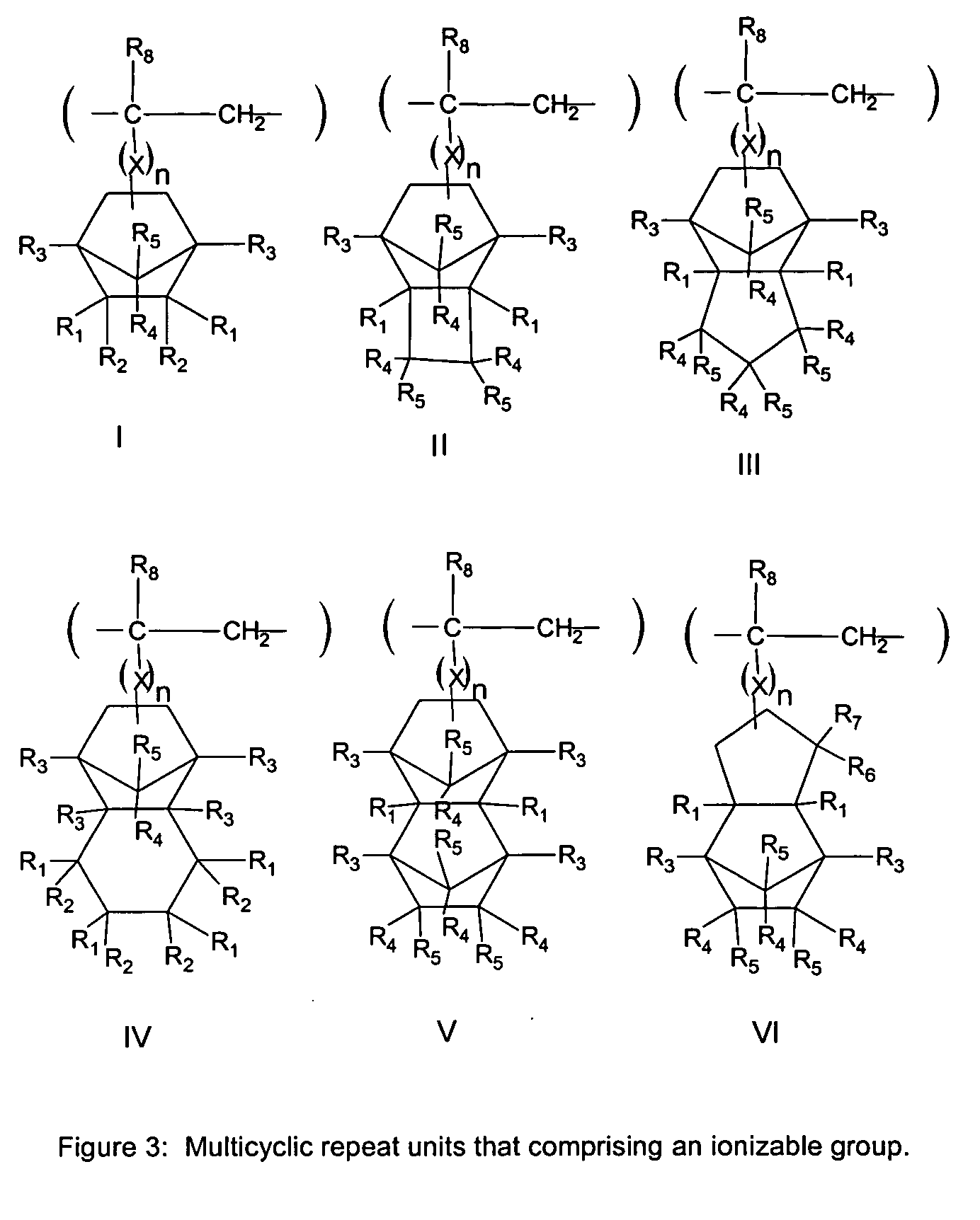
[0018] The invention further relates to the barrier coating solution for a deep ultraviolet photoresist imaged with immersion lithography, where the barrier coating is soluble in an aqueous alkaline solution and insoluble in water, and comprises an alkyl alcohol solvent and a polymer comprising an ionizable group, further where the pKa of the ionizable group ranges from about −9 to about 11. The invention also relates to a process for imaging a photoresist in the deep uv to prevent environmental contamination comprising the steps of, a) forming a coating of a photoresist on a substrate, b) forming a barrier coating over the photoresist from a barrier coating solution, c) imagewise exposing the photoresist and the barrier coating, and, d) developing the coatings with an aqueous alkaline solution, further wherein the barrier coating solution comprises a polymer comprising an acidic fluoroalcohol group and a solvent composition. In a preferred embodiment the polymer has a pKa of less than 9.

Problems solved by technology

Thus, treatment of a non-exposed negative-working photoresist with the developer causes removal of the unexposed areas of the coating and the formation of a negative image in the photoresist coating.
U.S. Pat. No. 5,843,624 discloses polymers for photoresist that are obtained by free radical polymerization of maleic anhydride and unsaturated cyclic monomers, but the presence of maleic anhydride makes these polymers insufficiently transparent at 157 nm.
These materials give acceptable absorbance at 157 nm, but due to their lower alicyclic content as compared to the fluoro-norbornene polymer, have lower plasma etch resistance.
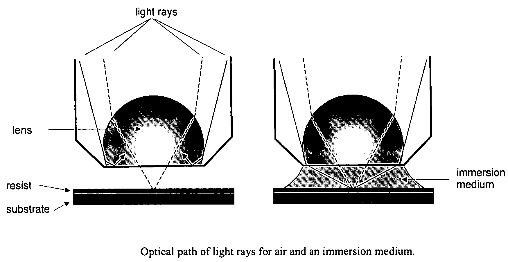
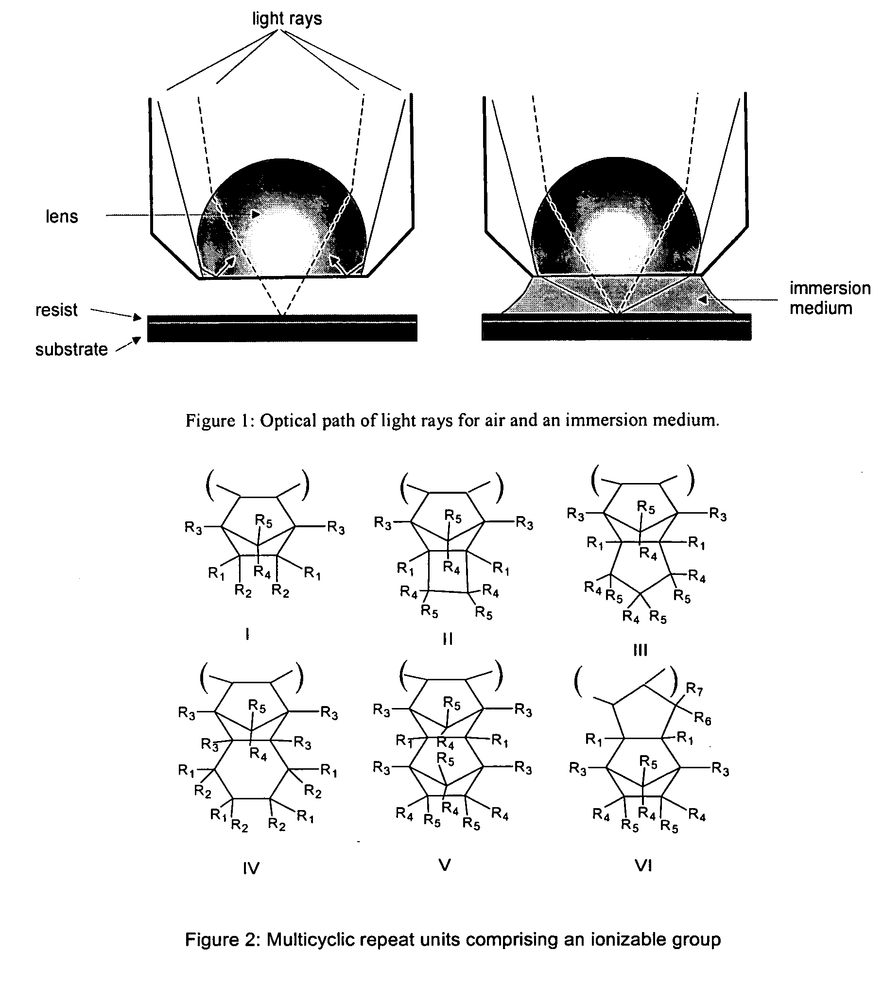
However, for 157 nm lithography, water's high absorbance makes it unsuitable as an immersion fluid.
The extraction of these materials is of concern for two reasons: firstly, it may affect resist performance deleteriously, and the second is the deposition of UV absorbing films on the objective lens in contact with the immersion fluid due to the photoreaction of extracted components in the immersion fluid.
It is also known that chemically amplified photoresists, especially those based on the catalytic deprotection of an acid labile group, are particularly sensitive to amine contamination from the environment.

Method used


Image

  • Process of imaging a deep ultraviolet photoresist with a top coating and materials thereof
  • Process of imaging a deep ultraviolet photoresist with a top coating and materials thereof
  • Process of imaging a deep ultraviolet photoresist with a top coating and materials thereof

Examples


example 1

Synthesis of Polymer for Barrier Coating 1

[0074] The polymer, F-1 BNC (DUVCOR 385) (available from Promerus LLC 9921 Brecksville Rd, Bldg B Breckville, Ohio, 44141) was added as a dry powder to a round bottomed flask containing a magnetic stirring bar. The flask was fitted with a stopcock inlet and a vacuum of at least 5 torr was applied slowly. The flask was then immersed in an oil bath and stirred. The oil bath was then heated up to a temperature of 180° C. and the powder stirred at this temperature for 2 hours. After cooling, the powder was recovered. NMR and Infrared spectroscopic (IR) analysis revealed that the t-butyl group in the polymer had been completely removed (IR Shift of C═O band and disappearance of the CH bands and C—O band for ester, and disappearance of the tert-butyl ester CH3 peak). The material was recovered with a 95% yield. The reaction scheme for this procedure is shown below.

example 2

Synthesis of F-1 tert-butoxycarbonylmethyl (BOCME) Precursor to Barrier Coat 2

[0075] The polymer F-1, poly(3-(bicyclo[2.2.1]hept-5-en-2-yl)-1,1,1-trifluoro-2-(trifluoromethyl)propan-2-ol) Mw (10,000), (available from Promerus LLC 9921 Brecksville Rd, Bldg B Breckville, Ohio, 44141) (4.0 g, 14.59 mmol) was dissolved in 15 ml of tetrahydrofuran (THF) and solid tetramethylammonium hydrxide, TMAH.5H2O (0.793 g, 4.38 mmol) was added while stirring. After 30 minutes, t-butyl bromoacetate (1.71 g, 8.76 mmol) was added to this solution which was stirred for another 16 hours at 25° C. The precipitate formed in the reaction mixture was removed by filtration. The resultant filtrate was stripped of solvents in a rotary evaporator. The resultant residue was redissolved in 20 ml of MeOH containing 1.0 g of concentrated HCl. This solution was precipitated in 180 ml of water-methanol (8:1) mixture. The polymer was isolated by filtration and further purified by dissolving it into MeOH and re-precip...

example 3

Synthesis of F-1-CH2CO2H Barrier Coat 2

[0076] The polymer, F-1-BOCME made in Example 2 was added as a dry powder to a round bottomed flask containing a magnetic stirring bar. The flask was fitted with a stopcock inlet and a vacuum of at least 5 torr was applied slowly. The flask was then immersed in an oil bath and stirred. The oil bath was then heated up to a temperature of 140° C. and the powder stirred at this temperature for 1 hour at the oil bath temperature was raised to 180° C. and the powder stirred and heated for another hour at this temperature. After cooling, the powder was recovered. Infrared spectroscopic (IR) analysis revealed that the t-butyl group in the polymer had been completely removed (IR Shift of C═O band and disappearance of the CH bands and C—O band for ester, and disappearance of the tert-butyl ester CH3 peak). The material was recovered with a 95% yield. The reaction scheme for this procedure is shown below.

Equipment Used for Coating and Patterned Expos...


PUM

PropertyMeasurementUnit
exposure wavelengthaaaaaaaaaa
pKaaaaaaaaaaa

Abstract

The present invention relates to a process for imaging deep ultraviolet (uv) photoresists with a topcoat using deep uv immersion lithography. The invention further relates to a topcoat composition comprising a polymer with at least one ionizable group having a pKa ranging from about −9 to about 11. The invention also relates to a process for imaging a photoresist with a top barrier coat to prevent contamination of the photoresist from environmental contaminants.

Description

FIELD OF INVENTION [0001] The present invention relates to a process for imaging deep ultraviolet (uv) photoresists with a topcoat using deep uv immersion lithography. The invention further relates to a topcoat composition comprising a polymer with at least one ionizable group having a pKa ranging from about −9 to about 11. The invention also relates to a process for imaging a deep uv photoresist with a top barrier coat to prevent environmental contamination of the photoresist, when exposure is done in air or other gases. BACKGROUND OF INVENTION [0002] Photoresist compositions are used in microlithography processes for making miniaturized electronic components such as in the fabrication of computer chips and integrated circuits. Generally, in these processes, a thin coating of film of a photoresist composition is first applied to a substrate material, such as silicon wafers used for making integrated circuits. The coated substrate is then baked to evaporate any solvent in the photor...

Claims


Application Information

Patent Timeline
Patent Type & Authority Applications(United States)
IPC IPC(8): G03C1/76G03F7/00G03F7/09G03F7/11G03F7/20
CPCG03F7/091G03F7/2041G03F7/11
Inventor HOULIHAN, FRANCIS M.DAMMEL, RALPH R.ROMANO, ANDREW R.SAKAMURI, RAJ
Owner AZ ELECTRONICS MATERIALS USA CORP
Why Eureka
Try Eureka